


UDC Mini-Converter v2.3r1
www.aja.com
18
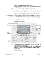
HDMI Tab Screen
Provides user selection of the HDMI output modes. There is no DIP switch equivalent for
these controls. The setting is saved in nonvolatile memory in the module and used for all
subsequent operation.
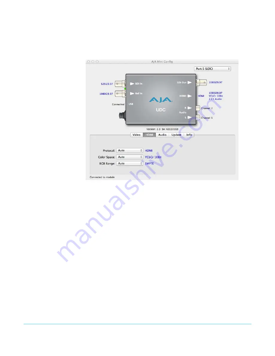
Figure 12. Mini Config, HDMI Screen
HDMI Video Output
: The HDMI video output always mirrors the SDI video output, both
in content and output format selection.
NOTE:
When the output format is set to 1080psf23.98 or 1080psf24 the HDMI output is disabled
since HDMI does not have a corresponding supported format.
Protocol
: Selects whether the HDMI output uses DVI or HDMI protocols for sending
video to the destination device. These are the choices:
Auto
: UDC automatically selects the output protocol based on getting the attached
HDMI device's EDID information. This is the recommended setting. The selected
protocol is shown to the right of the popup control.
HDMI
: UDC uses HDMI protocols regardless of the attached device's EDID.
DVI
: UDC uses DVI protocols regardless of the attached device's EDID. Because DVI
protocols do not support audio or HDMI InfoFrame ancillary data, select this mode
only if you know that the attached device requires it.
Color Space
: Selects the HDMI output color space and depth. These are the choices:
Auto
: UDC automatically selects the mode based on getting the attached HDMI
device's EDID information. This is the recommended setting. The selected mode is
shown to the right of the pull-down control.
RGB 8Bit
: UDC uses 8-bit RGB mode regardless of the attached device's EDID.
RGB 10Bit
: UDC uses 10-bit RGB mode regardless of the attached device's EDID.
YCbCr 10Bit
: UDC uses 10-bit YCbCr mode regardless of the attached device's EDID.