


1
5
AJA R44E 4-CH Monitoring Encoder User Manual
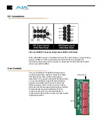
Control Functions
Installation
Typically, R44E installation consists of the following:
1.
disconnect power from the frame (remove line cord)
2.
remove the FR1/FR2 front panel
3.
install R44E card module
4.
replace the FR1/FR2 front panel
5.
apply power to the frame by connecting a north american-style power cord from
the frame to mains power (90 to 260 VAC)
!
Warning!
Ensure Mains Power is disconnected before installing the FR1 or FR2 frame R-series
modules into the frame, or installing and removing options. If a Mains switch is not
provided, the power cord(s) of this equipment provide the means of disconnection.
The socket outlet must be installed near the equipment and must be easily
accessible.
Warning!
FR2 Dual Power Cord Notice—please read this. To reduce the risk of electrical shock,
disconnect both power cords before servicing equipment.
Caution!
The FR1/FR2 front fan door is heavy and is not hinged. Remove with Caution.
Instructions for removing the frame front door for module installation is discussed in
the
FR1/FR2 User Manual.
Switch
Position
Function
S1 Y/C:
ON (Down): output is Y (luminance)
OFF (Up): output is composite (NTSC or PAL)
S2 BLNK:
NAR (Up):
Vertical (line numbers indicate where video starts)
line 13, field 1; line 12, field 2 (525 line)32
line 10, field 1; line 322, field 2 (625 line)
Horizontal (active video line durations)
ITU-R.470 (720 pixels PAL/NTSC)
WIDE (Down):
Vertical (line numbers indicate where video starts)
line 22, field 1; line 21, field 2 (525 line)
line 23, field 1; line 335, field 2 (625 line)32
Horizontal (active video line durations)
ITU-R/SMPTE (710 pixels NTSC, 702 pixels PAL)
S3 PEDESTAL:
ON (Up): 7.5 IRE pedestal for NTSC
OFF (Down): No pedestal
NOTE: this has no effect with 625 input
S4 TEST:
ON (Down): Internal 75% Color Bars test pattern output
OFF (Up): Normal operation
Содержание R44E
Страница 14: ...14...


