


HD10MD4 Mini-Converter v1.1r2 5
www.aja.com
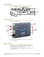
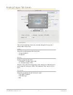
Block Diagram
Figure 1. HD10MD4 Mini-Converter, Simplified Block Diagram
Component/
Composite Outputs
(selected by DIP switch
or Mini-Config)
HD or SD
SDI Input
De-serializer
Cable EQ
SD SDI Output
Y G Composite
Pb B Y
Pr R C
D/A
Conversion
H & V
Filtering and
Decimation
Audio
Embedding
Embedded
Audio
Extraction
Delay
Serializer
HD-SDI Out 1
USB
Port
Config
Control
DIP
Switch
Settings
3:2 Pulldown Synchronization
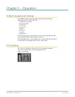
I/O Connections
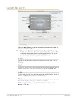
Figure 2. HD10MD4 Mini-Converter
DC Power
Input
SD-SDI
Output
BNC
HD-SDI
Input BNC
Composite
Component
Output BNCs (3)
USB Port
Lock LED
HD-SDI
Loop Output
BNC
NOTE: The Lock LED indicates valid input video by color. Off is no input, green is SD
video, red is HD video.
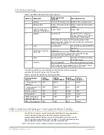
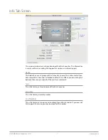
User Controls
The direct user interface for the HD10MD4 is an eight position DIP switch
accessible through a cut-out in the bottom of the unit. The exact function of the
DIP switches are described in
The HD10MD4 also supports Mini-Config application control over its USB port to
a connected PC or Mac.


