


4
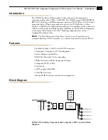
I/O Connections
D10AD, Side View
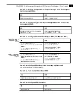
User Controls
The user interface for the D10AD is an 8-
switch DIP accessible through a cut-out in the
bottom of the unit. Use the DIP switches to
configure outputs, pedestal, blanking, and
enable or disable comb filter, EDH, AGC, and
test pattern.
Switches 1 and 2 select composite or
component input and the type of component
input. Switches 3 through 8 set configuration
features. The exact function of each DIP
switch and what it controls is described on the
following pages.
Note:
Changing input format (SW1, SW2, or SW3) causes a reset to occur that
takes about 10 seconds to complete.
+ 5VDC
Power
Input
Serial
Digital
Outputs
4 BNCs
Composite/
Component
Inputs
Configuration
determined by
DIP switch on
other side of
Converter
DIP Switches
1
2
3
4
5
6
7
8
OFF ON
Test Equipment Depot - 800.517.8431 - 99 Washington Street Melrose, MA 02176 - FAX 781.665.0780 - TestEquipmentDepot.com