


ADA4 Mini-Converter v1.0r2
www.aja.com
9
Chapter 2: ADA4 Operation
Internal Jumpers
Jumpers inside the case determines whether the unit operates as an AD/DA audio
converter (Normal mode, the default setting) or as a Synchronizer, and whether the ADA4
Mini-Converter’s digital outputs are 48k (the default setting) or 96k.
NOTE:
If you will be using the ADA4 as an A/D D/A converter with 48k outputs, no jumper changes
are required. Configuration is accomplished using the external DIP switches.
To access the internal jumpers, remove the four Phillips screws securing the back side of
the ADA4 case (the side having the DIP switch access hole in it). Once the case cover is
removed, jumper positions 1 through 3 are clearly marked on the circuit board next to
the jumper.
48 KHz/96KHz
Output Mode
(Jumper #1)
Jumper #1 selects the AES outputs and the AES11 reference output sample rates.
• When Jumper 1 is installed, they run at 48 KHz.
• When Jumper 1 is removed, they run at 96 KHz.
Normal/
Synchronizer Mode
(Jumper #2)
Jumper #2 selects Normal or Synchronizer operating mode.
• When Jumper 2 is installed, the ADA4 runs in Normal node, and the ADA4 DIP switches
are available for configuration.
• When Jumper 2 is removed, the ADA4 runs in Synchronizer mode. Synchronizer mode
is an alternative operating mode where no audio A/D or D/A conversion takes place.
Instead, it allows for an AES input to be sample rate converted and reclocked to reveal
an AES output that is low jitter, and—when a reference signal is applied—locked to
reference. Without a reference signal applied, the ADA4 reclocks the output based on
its stable, free-running local oscillator. In this mode the DIP switches are ignored.
Jumper #3
Jumper #3 is currently unused.
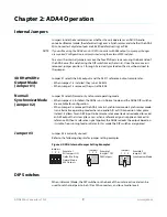
Refer to the following diagram for jumper setting examples
Figure 4. ADA4, Internal Jumper Setting Examples.
DIP Switches
When in Normal Mode, the DIP switches on the back of the unit are active and can be
used to set channel pairs to be A/D or D/A converters, and to set audio levels.
Jumpers
Example 1
All Jumpers ON
Default Setting
Normal Mode
48k Outputs
1 2 3
Jumpers Example 2
Jumper 1 OFF
96k Outputs
1 2 3
Jumpers
Example 3
Jumper 2 OFF
Synchronizer Mode
1 2 3


