


– 48 –
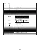
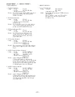
< TUNER SECTION >
1. Clock Frequency Check
Settings :
• Test point :
TP2 (CLK)
Method :
Set to MW 1602kHz and check that the test
point is 2052kHz
±
45Hz.
2. MW VT Check
Settings :
• Test point :
TP1 (VT)
Method :
Set to MW 1602kHz and check that the test point is
less than 8.0V. Then set to MW 531kHz and check that
the test point is more than 0.6V.
3. MW Tracking Adjustment
Settings :
• Test point :
TP8 (Lch), TP9 (Rch)
• Adjustment location : L981 (1/3)
Method :
Set to MW 999kHz and adjust L981 (1/3) so
that the test point becomes maximum.
4. LW VT Adjustment
Settings :
• Test point :
TP1 (VT)
• Adjustment location : L942
Method :
Set to LW 144kHz and adjust L942 so that the test
point becomes 1.3V
±
0.05V.
Then set to LW 290kHz and check that the test point is
less than 8.0V.
5. LW Tracking Adjustment
Settings :
• Test point :
TP8 (Lch), TP9 (Rch)
• Adjustment location :
L941 ........................... 144kHz
TC942 ......................... 290kHz
Method :
Set up TC942 to center before adjustment.
The level at 144kHz is adjusted to MAX by
L941. Then the level at 290kHz is adjusted
to MAX by TC942.
6. AM IF Adjustment
Settings :
• Test point :
TP8 (Lch), TP9 (Rch)
• Adjustment location :
L772 ........................... 450kHz
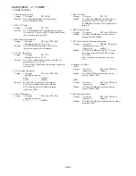
7. FM VT Check
Settings :
• Test point :
TP1 (VT)
Method :
Set to FM 108.0MHz and check that the test
point is less than 8.0V. Then set to FM
87.5MHz and check that the test point is more
than 0.5V.
8. FM Tracking Check
Settings :
• Test point :
TP8 (Lch), TP9 (Rch)
Method :
Set to FM 98.0MHz and check that the test
point is less than 13dB
µ
V.
9. DC Balance / Mono Distortion Adjustment
Settings :
• Test point :
TP3,TP4 (DC balance)
• Adjustment location : L771
• Input level :
60dB
µ
V
Method :
Set to FM 98.0MHz and adjust L771 so that
the voltage between TP3 and TP4 becomes
0V
±
0.04V.
Next, check that the distortion is less than
1.3%.
10. Output Level Check
<MW>
Settings :
• Test point :
TP8 (Lch), TP9 (Rch)
• Input level :
74dB
µ
V
Method :
Set to MW 999kHz and check that the test
point is 130mV
±
3dB.
<FM>
Settings :
• Test point :
TP8 (Lch), TP9 (Rch)
• Input level :
60dB
µ
V
Method :
Set to FM 98.0MHz and check that the test
point is 520mV
±
3dB.
11. FM Separation Check
Settings :
• Test point :
TP8 (Lch), TP9 (Rch)
• Input level :
60dB
µ
V
Method :
Set to FM 98.0MHz and check that the test point is
more than 12dB.
ADJUSTMENT – 2 <TUNER>
Содержание XH-A1000
Страница 19: ... 19 SCHEMATIC DIAGRAM 1 MAIN 1 4 AMP SECTION CONNECT 1 3 ...
Страница 20: ... 20 SCHEMATIC DIAGRAM 2 MAIN 2 4 POWER SUPPLY SECTION ...
Страница 21: ... 21 SCHEMATIC DIAGRAM 3 MAIN 3 4 DECK SECTION ...
Страница 22: ... 22 SCHEMATIC DIAGRAM 4 MAIN 4 4 PRO LOGIC SECTION ...
Страница 23: ... 23 SCHEMATIC DIAGRAM 5 FAN ...
Страница 25: ... 25 SCHEMATIC DIAGRAM 6 FRONT CONNECT 2 3 DECK DECK MOTOR ...
Страница 27: ... 27 SCHEMATIC DIAGRAM 7 OPERATE KEY MIC LED A D ...
Страница 29: ... 29 SCHEMATIC DIAGRAM 8 LOW AMP ...
Страница 31: ... 31 SCHEMATIC DIAGRAM 9 5CH AMP ...
Страница 33: ... 33 SCHEMATIC DIAGRAM 10 VIDEO I O VIDEO JACK VIDEO 3 CONNECT 3 3 ...
Страница 34: ... 34 SCHEMATIC DIAGRAM 11 SCART ...
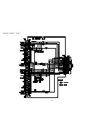
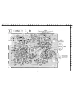
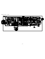
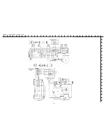
Страница 36: ... 36 SCHEMATIC DIAGRAM 12 TUNER ...
Страница 38: ... 38 SCHEMATIC DIAGRAM 13 PT ...
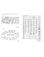
Страница 40: ... 40 FL BJ733GK GRID ASSIGINMENT ANODE CONNECTION PIN CONNECTION ...
Страница 41: ... 41 FL BJ734GK GRID ASSIGINMENT ANODE CONNECTION PIN CONNECTION ...
Страница 42: ...IC BLOCK DIAGRAM 42 ...
Страница 43: ... 43 ...
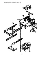
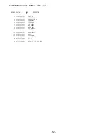
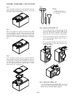
Страница 51: ... 51 TAPE MECHANISM EXPLODED VIEW 1 2 a 6ZM 4 R3 P C B a 1 2 3 4 5 BASE MECHA 6 7 8 9 10 11 12 13 B A C C ...
Страница 58: ...2 11 IKENOHATA 1 CHOME TAITO KU TOKYO 110 JAPAN TEL 03 3827 3111 Printed in Singapore 9620450 0251431 ...


