


AIWA VX-T1480
Mechanical Adjustments
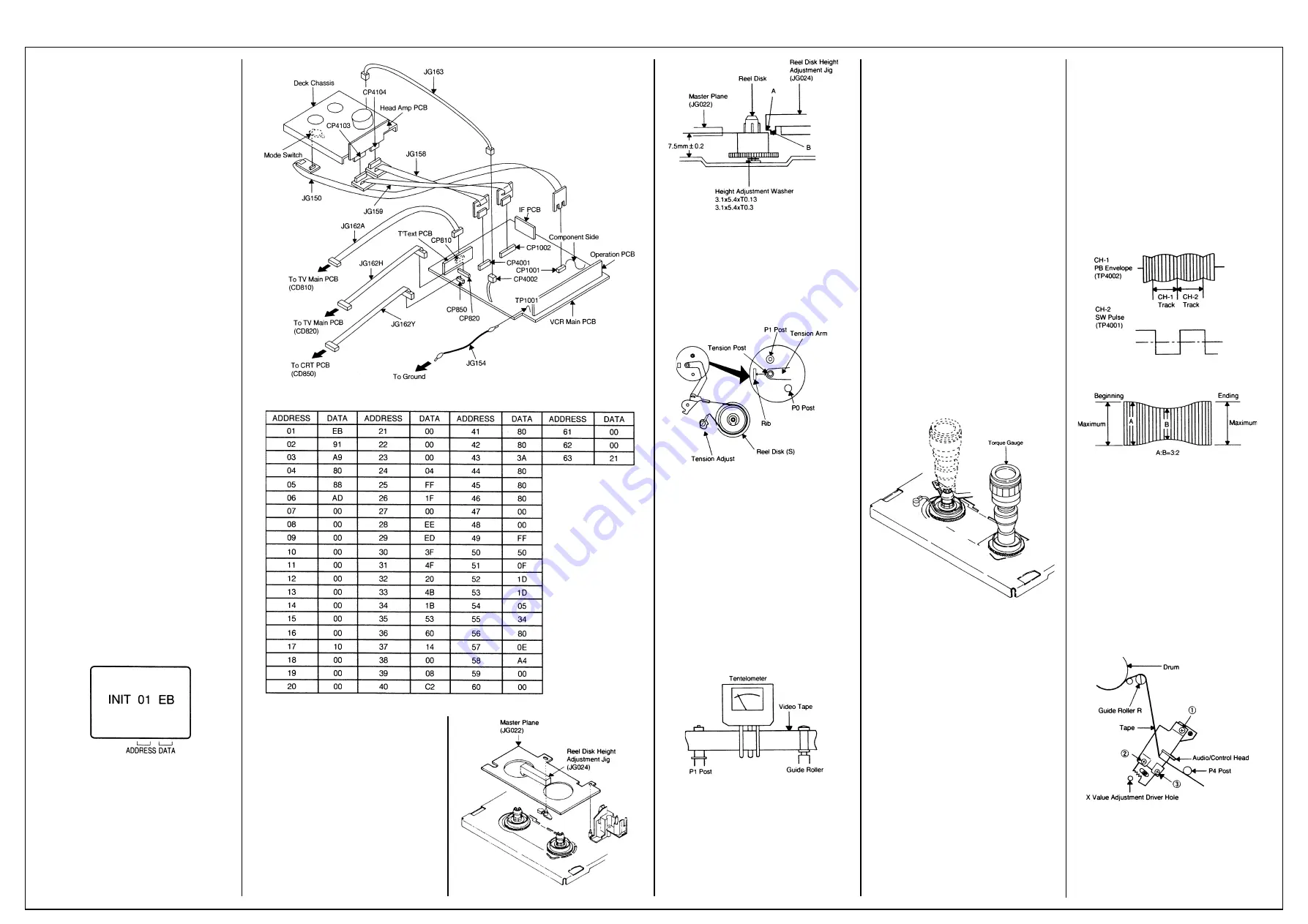
SERVICING PREPARATION
How to use the servicing fixture
1. Remove the VCR Main PCB from the Deck
Chassis.
2. Connect as shown in the figure using the
Service Fixture.
• Connect the VCR Main PCB to the Mode
Switch with the cable JG150.
• Connect the VCR Main PCB to the Head Amp
PCB with the cable JG158 and JG159.
• Connect the VCR Main PCB to the TV Main
PCB with the cable JG162A and JG 162H.
• Connect the VCR Main PCB to the CRT PCB
with the cable JG162Y.
• Connect the VCR Main PCB to the FE Head
with the cable JG163.
3. Short circuit between TP1001 and Ground
with the cable JG154. (Refer to MAJOR
COMPONENTS LOCATION GUIDE)
4. The EOT, BOT and Reel Sensor do not work
at this moment.
5. At that time, the STOP/EJECT button is
available to insert and eject the Cassette
Tape.
INSTRUCTIONS
1. Unplug the AC cord once and the clock will be
non-setting.
2. Turn on the POWER and set the VOLUME to
minimum.
NOTE:
If the Auto Set Up Function is working, the unit
cannot be operated. In this case, release the
Function or wait until the Function goes to the
end.
3. Press the VOL. DOWN button on the set and
the Channel button (6) on the remote control
simultaneously. The Fig. 1 appears on the
display.
4. Press the SET +/- button on the remote
control to modify the address and check the
data.
(Refer to Table 1)
5. After checking, turn off the Power.
(If the wrong data is input)
6. Press the SET +/- button on the remote
control to set to the address of the wrong
data, then press the ENTER button. The data
will bink. (Refer to Fig. 1)
7. Press the SET +/- button on the remote
control to set to the correct data, then press
the ENTER button. (Refer to Table 1)
8. Repeat the above steps 6 and 7 and input the
data into the each Address.
9. After the data input, turn off the Power.
Fig. 1
1. CONFIRMATION AND ADJUSTMENT
Read the following NOTED items before starting
work.
• Place an object which weighs between 350g
and 500g on the Cassette Tape to keep it
steady when you want to make the tape run
without the Front Loading Unit 6. (Do not
place an object which weighs over 500g.)
Reel Disk (S)
• When you activate the deck without the Front
Loading Unit 6, short circuit between TP1001
and Ground. In this condition the BOT/EOT/
Reel Sensor will not function.
1-1: CONFIRMATION AND ADJUSTMENT OF
REEL DISK HEIGHT
1. Turn on the power and set to the STOP
mode.
2. Set the master plane (JG022) and reel disk
height adjustment jig (JG024) on mechanism
framework, taking care not to scratch the
drum, as shown in Fig. 1-1-A.
3. Confirm that the reel disk is lower than “A” of
the reel disk height adjustment jig (JG024) on
the master plane and higher than “B” as
shown in Fig. 1-1-B. If it is not, adjust to less
than 7.5mm
±
0.2mm with the height adjust-
ment washer.
4. Perform the same adjustment for other reel.
Fig. 1-1-A
Fig. 1-1-B
1-2: CONFIRMATION AND ADJUSTMENT OF
TENSION POST POSITION
1. Turn on the power and set to the PLAY mode
adjust the Tension so that the Tension Post is
at the position of 0.3mm~0.5mm from the Rib.
(Refer to Fig. 1-2)
2. Confirm that the video tape is not curling at
the flange of P1 post or is not running on
flanges.
Fig. 1-2
1-3: CONFIRMATION AND ADJUSTMENT OF
BACK TENSION ON PLAYBACK
1. Load a video tape recorded in standard speed
mode. Set the unit to the PLAY mode.
2. Install the tentelometer as shown in Fig. 1-3.
Confirm the value is within 20~27gr/cm at this
time.
IN CASE OF USING A CASSETTE TYPE
TORQUE TAPE.
1. After adjustment, confirm and adjust the
tension post position (Refer to item 1-2) for
the tension arm, install the cassette type
torque tape (JG100A) and set to the PLAY
mode.
2. Confirm that the left hand side tension value
of the torque tape is 25~38gr/cm for the
standard mode tape.
Fig. 1-3
1-4: CONFIRMATION OF FAST FORWARD
TORQUE
1. Set torque gauge (JG002G) on take-up reel
disk, and place unit in FAST FORWARD
mode. (Refer to Fig. 1-4)
2. Confirm that torque is more than 400gr/cm.
NOTE
After setting the torque gauge on the reel disk,
hold the gauge in place. Push the FAST
FORWARD button and the reel disk will begin to
turn.
1-5: CONFIRMATION OF REWIND TORQUE
1. Operate within 4 or 5 seconds after the reel
disk begins to turn.
2. Set torque gauge (JG002G) on supply reel
disk, and place the unit in REWIND mode.
(Refer to Fig 1-4).
3. Confirm that torque is more than 400gr/cm.
NOTE
After setting the torque gauge on the reel disk,
hold the gauge in place.
Push the REWIND button and the reel disk will
begin to turn.
1-6: CONFIRMATION OF REEL BRAKE
TORQUE
(Take-Up Reel Brake) (Refer to Fig. 1-4)
1. Set to STOP mode.
2. Set the torque gauge (JG002G) to the take-
up reel and turn it counterclockwise.
3. Confirm that it is more than 200gr/cm at that
time.
(Supply Reel Brake) (Refer to Fig. 1-4)
1. Set to STOP mode.
2. Set the torque gauge (JG002G) to the supply
reel and turn it clockwise.
3. Confirm that it is more than 200gr/cm at that
time.
NOTE
Separate the idler from the reel and confirm the
brake torque.
Fig. 1-4
2-1: GUIDE ROLLER
NOTE
If the torque value checked is out of tolerance,
replace the appropriate parts as follows.
Check Items
Replace Parts
1-4
Idler Ass’y or Clutch Ass’y
1-5
Idler Ass’y or Clutch Ass’y
1-6
Main Brake T Ass’y or Main Brake S Ass’y
2. TAPE RUNNING CONFIRMATION AND
ADJUSTMENT
Tape running is adjusted precisely at the factory.
Normally, it is not necessary to make adjust-
ments. It is necessary to confirm and make
adjustments when the parts of the tape running
mechanism are replaced because of extensive
usage or failure.
2-1: GUIDE ROLLER
1. Connect CH-1 on the oscilloscope to TP4002
(PB Envelope) and CH-2 to TP4001 (SW
Pulse).
2. Set the tracking to manual center position in
the following way. Press and hold the tracking
auto button more than 2 seconds to set the
tracking to center position.
3. Trigger with SW pulse and observe the
envelope. (Refer to Fig. 2-1-A)
4. Adjust the guide roller height while observing
the envelope, and make the envelope flat.
Adjust the envelope so that the flatness will
not be affected even when the tracking control
button is pressed. (Use the adjustment
screwdriver JG005).
5. Press and hold the tracking control button
and (at the point that the envelope waveform
starts to reduce) adjust the envelope so that
the A:B ratio is better than 3:2. (Refer to Fig.
2-1-B)
6. Adjust the PG shifter (ELECTRICAL ADJUST-
MENTS : ITEM 3-1) in the PLAY mode.
NOTE
After adjustment, confirm and adjust A/C head
tilt. (Refer to item 2-2)
Fig. 2-1-A
Fig. 2-1-B
2-2: CONFIRMATION AND ADJUSTMENT OF
A/C HEAD TILT
When the tape is running abnormally, perform
the following adjustments.
1. Insert a new tape and play it back.
2. Confirm that there is no crease on the tape
between the P4 post and guide roller (R) and
the tape is running smoothly. (It is absolutely
impossible to get satisfactory sound if the
tape is distorted between the A/C head and
P4 post.)
3. If the tape still does not run smoothly, turn the
screw (1) and adjust the tilt of the A/C head.
(Refer to Fig. 2-2)
Fig. 2-2
2-3: ADJUSTMENT OF A/C HEAD HEIGHT
AND AZIMUTH
1. Playback a VHS alignment tape (JG001C)
and observe the waveform at the audio output
terminal.
2. Turn the screw (2) slowly to change the
Содержание VX-T1480
Страница 6: ...AIWA VX T1480 OVD 5 Deck Alternative Parts Cont d...
Страница 7: ...AIWA VX T1480 OVD 5 Deck Alternative Parts Cont d Earphone Diagram...
Страница 9: ...AIWA VX T1480 Chroma Diagram...
Страница 10: ...AIWA VX T1480 CRT Diagram...
Страница 11: ...AIWA VX T1480 Deflection Diagram...
Страница 12: ...AIWA VX T1480 Microcontroller Diagram...
Страница 13: ...AIWA VX T1480 Head Amp Diagram...
Страница 14: ...AIWA VX T1480 IF PCB Diagram...
Страница 15: ...AIWA VX T1480 Operations Diagram 1...
Страница 16: ...AIWA VX T1480 Operations Diagram 2 Audio Amp Diagram...
Страница 17: ...AIWA VX T1480 Power Diagram TV...
Страница 18: ...AIWA VX T1480 Power Diagram VCR...
Страница 19: ...AIWA VX T1480 Teletext Diagram...
Страница 20: ...AIWA VX T1480 Y C Diagram...
Страница 21: ...AIWA VX T1480 Tuner Audio Diagram...
Страница 22: ...AIWA VX T1480 Waveforms...
Страница 23: ...AIWA VX T1480 Wiring Diagram...
Страница 24: ...AIWA VX T1480 System Control Servo Diagram...


