


-33-
ELECTRICAL ADJUSTMENT -3/7
<MW/LW Adjustment>
Make the following preparations for MW/LW adjustment.
Preparations
•
Standard Signal Generator (S.S.G.) / Loop antenna / Oscilloscope / Millivoltmeter / Dummy resistance (6y)
1) Connect the unit and measuring instruments as shown in the diagram below.
2) Position the loop antenna connected to S.S.G. and the one connected to the unit 60 cm apart.
5. IF Adjustment (MW)
Requirements: As instructed in preparations.
•
Adjustment point: L802
1) Set S.S.G. to MW; carrier of 999 kHz with 30% modulation, and source at 1 kHz, position output at maximum.
2) Tune the receiving frequency of the unit at MW 999 kHz.
3) While monitoring the waveform at 1 kHz through the oscilloscope, lower the output level of S.S.G. maximum (till a certain degree of
noise is monitored).
4) Adjust L802 so that the millivoltmeter points maximum.
6. Tracking Adjustment (MW)
Requirements: As instructed in preparations.
•
Adjustment point: L952 / L953
1) Set S.S.G. to MW; carrier of 999 kHz with 30% modulation, and source at 1 kHz, position output at maximum.
2) Tune the receiving frequency of the unit at MW 999 kHz.
3) While monitoring the waveform at 1kHz through the oscilloscope, lower the output level of S.S.G. maximum (till a certain degree of
noise is monitored).
4) Adjust L952 so that the millivoltmeter points maximum.
5) Set S.S.G. to MW; carrier of 603 kHz with 30% modulation, and source at 1 kHz.
6) Tune the receiving frequency of the unit at MW 603 kHz.
7) Adjust L953 so that the millivoltmeter points maximum.
8) Repeat above steps 1) to 7) 2 to 3 times.
7. Tracking Adjustment(LW)
Requirements: As instructed in preparations.
•
Adjustment point: L941/TC942
1) Set S.S.G. to LW; carrier of 144 kHz with 30% modulation, and source at 1 kHz, position output at maximum.
2) Tune the receiving frequency of the unit at LW144 kHz.
3) While monitoring the waveform at 1kHz through the oscilloscope, lower the output level of S.S.G. maximum (till a certain degree of
noise is monitored).
4) Adjust L941 so that the millivoltmeter points maximum.
5) Set S.S.G. to LW; carrier of 290 kHz with 30% modulation, and source at 1 kHz.
6) Tune the receiving frequency of the unit at LW 290 kHz.
7) Adjust TC942 so that the millivoltmeter points maximum.
8) Repeat above steps 1) to 7) 2 to 3 times.
8. Auto-Stop Check (MW)
Requirements: As instructed in preparations.
1) Set S.S.G. to MW; carrier of 999 kHz with 30% modulation, source at 1 kHz, and output of 40 to 65 dBuV.
2) Apply the tuning search function, and check that the unit automatically stops at MW 999 kHz.
´
d u
p a
t o
r
Содержание NSX-R20 - SERVICE
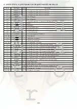
Страница 39: ... 39 LCD DISPLAY 1 1 GRID ASSIGNMENT ANODE CONNECTION PIN CONNECTION d u p a t o r ...
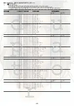
Страница 40: ... 40 IC BLOCK DIAGRAM 1 3 IC BD3881FV IC NJM7806FA d u p a t o r ...
Страница 41: ... 41 IC BLOCK DIAGRAM 1 3 IC LA1845N A IC LC7213D N d u p a t o r ...
Страница 42: ... 42 IC BLOCK DIAGRAM 3 3 IC BU1920FS d u p a t o r ...
Страница 53: ...2 11 IKENOHATA 1 CHOME TAITO KU TOKYO 110 8710 JAPAN TEL 03 3827 3111 0251431 d u p a t o r ...


