background image

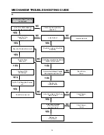
MECHANISM TROUBLESHOOTING  GUIDE

72

In PB mode Tape Presence

not sensed.

Is the Pinch Roller attached 

to the Capstan Motor Shaft?

Check Alignment positions

(page 61)

Does the T/Up 

Reel turn?

Replace the Belt.

Is the Belt ok?

Does the Drum 

Motor turn?

Are there DPG, 

DFG Pulses?

Are the T/Up Supply Reel Sensors

ok?

Check Syscon,

Circuit.

Check Syscon,

Circuit.

Check Servo, Syscon.

Does the Capstan Motor turn?

Is the terminal voltage 

of the Drum Motor 

more than  2.3V?

Replace the 

Drum Motor.

Is the Vcc voltage of the Drum

Motor normal?

Check the clutch and the Idler

Assembly.

YES

YES

YES

YES

YES

YES

YES

YES

NO

NO

NO

NO

NO

Is the terminal voltage of Capstan

Motor supplied more than 4V?

Replace the 

Capstan Motor.

Is the Voltage supplied to the Capstan

Motor Vcc1,Vcc2 each?

YES

YES

YES

Check Servo,

Power.

NO

NO

NO

E.

Содержание HV-FX780

Страница 1: ...DER HV FX780 S M Code No 09 999 335 6R1 NH SERVICE MANUAL D A T A BASIC TAPE MECHANISM D 33 6721R 0122A R E V I S I O N This Service Manual is the Revision Publishing and replaces Simple Manual S M Co...

Страница 2: ...Capstan Motor Capstan 55 21 Clutch Assembly D33 55 22 Lever F R 55 23 Gear Assembly H UP D or Gear Assembly UP D 55 24 Bracket Assembly Jog 56 25 Guide Rack F L Gear Rack F L 56 26 Brake Assembly Cap...

Страница 3: ...y EP 9 hours with T 180 tape Tape speed SP 33 35 mm sec LP 16 67 mm sec EP 11 12 mm sec Fast forward Rewind time Less than 180 seconds with T 120 tape Channel coverage VHF 2 to 13 UHF 14 to 69 CATV 4A...

Страница 4: ...direction of arrow 2 Fig 2 4 Mechanism Removal see Fig 3 1 Disconnect the drum FF cable from the connector PMD01 on the Main C B 2 Disconnect the ACE head FF cable from the connector P3D02 on the Mai...

Страница 5: ...ny defective contact Location Install spacers at locations A and B MAIN C B D33 MECHANISM SPACER 60mm MAIN C B D33 MECHA SPACER REAR PANEL Use a spacer with a diameter of 10 15 mm and of any shape rou...

Страница 6: ...z CH 1B 2 NTSC Stairsteps 1 kHz SP No Changed NTSC Color bar 1 kHz EP CH 1B 4 2 No Changed CH 1B 1 NTSC Stairsteps 7 kHz SP CH 1B 4 NTSC Color bar 1 kHz EP No Changed CH 1B 3 NTSC Color bar No sound S...

Страница 7: ...50V C332 87 010 544 010 CAP E 0 1 50V C335 87 016 088 040 CAP E 220 6 3V C342 87 015 684 080 CAP E 47 16V C345 87 015 698 080 CAP E 4 7M 50V C347 87 015 698 080 CAP E 4 7M 50V C350 87 015 695 080 CAP...

Страница 8: ...TAL 10MHZ 30PPM X502 S5 290 01K 000 X TAL 32 768KHZ X502 S5 290 01B 000 X TAL 32 768KHZ X503 S2 02R 114 3AA X TAL 14 317872 X503 S2 02R 114 3AC X TAL 14 317872MHZ X503 S2 02R 114 3AE X TAL 14 317872MH...

Страница 9: ...S1 MODE S2 MODE S3 MODE S4 1 2 3 4 5 1 2 GND FULLERASE 1 2 LOWER DRUM CAPSTAN MOTOR MS501 MODE SW FULL ERASE HEAD CYL HEAD MAIN C B FRONT 2 C B FRONT 1 C B ACE HEAD PMD01 PMC01 P3D02 MS501 P3D03 1 2...

Страница 10: ...OCK R116 R117 R118 R119 R120 R121 C114 RECTIFIER SMOOTHING RECTIFIER SMOOTHING DRIVE OVER CURRENT LIMIT BLOCK C1J1 12 3V CAP 29VA FD FD 36V 9V 12V DRUM 5 1VA 5 3VA 5 1V D SNUBBER BLOCK Q112 D102 D103...

Страница 11: ...AUDIO REC PB HEAD AUDIO REC PB HEAD AUDIO ERASE HEAD REC AUDIO SIGNAL PB AUDIO SIGNAL 17 A OUT 17 A IN TU701 TUNER JK301 AUDIO IN JK301 AUDIO OUT BIAS OSC FL301 Q301 SW Q302 Q303 SW Q304 Q306 FULL ER...

Страница 12: ...V DATA CLOCK ENABLE N C RF AGC V IN CONTROL REG 5V CH S W A IN BUFFER Q701 VIDEO VCR H CLOCK AFT TU VIDEO 36V 5 1V A DATA TU AUDIO MOD A IN LINE VIDEO VHF UHF IN FROM ANT OUT TO TV From SYSCON SERVO S...

Страница 13: ...interface X tal VCO OSC TRAP FM AGC P EQ G EQ D LIM Y LPF Main De Empf DEMO S LPF 2M LPF ACC CTL Trap fh Trap HIFI Trap C LPF DEALY MIX AMP SQUEL CH CLEAR SYNC CLAMP CLAMP Sharpness CONTROL YNR NC SY...

Страница 14: ...SC2 X1 X2 OSC1 70 69 53 52 50 fsc IN 13 KEY RTN 0 14 KEY RTN 1 fsc OUT Dosc IN 19 LD LD 20 31 32 38 40 61 80 81 12 24 87 26 39 27 25 78 DRUM PWM 42 Vcc OSD 3 SUP END Sensor 51 Dosc OUT 82 15 Vcc A D 9...

Страница 15: ...risk of fire or NOTES electricial shock MAIN POWER SECTION C B AC120V 60Hz C101 0 1u 275V ICP N20 ICP N20 0 8A 50V 12 3V CAP To AUDIO VIDEO SECTION To TUNER IF SECTION Front SYSCON SERVO SECTION To SY...

Страница 16: ...1 2 2 2 4 2 8 2 1 1 4 2 1 0 2 8 1 9 2 8 0 0 0 2 7 2 7 1 7 5 1 5 1 5 1 5 1 5 1 2 5 0 0 0 0 2 8 1 9 2 1 2 8 2 8 2 8 2 8 5 0 2 3 0 5 0 5 0 0 2 5 2 5 2 1 2 2 2 1 2 7 2 1 2 8 2 1 1 9 1 1 0 0 5 1 5 0 2 5 2...

Страница 17: ...IC301 Pin 100mV 0 2msec DIV REC PB 2fsc 1 2 3 4 5 6 7 8 9 0 IC301 Pin 50 1 0mV 20 sec DIV VV EE C SYNC OUT IC301 Pin 52 500mV 10 sec DIV VV EE VIDEO OUT IC301 Pin 54 220mV 20 sec DIV PB C OUT IC301 P...

Страница 18: ...YNC IC501 Pin 1V 10msec DIV REC CTL IC501Pin 1V 10msec DIV REC CTL IC501 Pin 1V 1msec DIV REC PB DFG IC501 Pin 1V 10 sec DIV REC PB DPG IC501 Pin 500mV 10 sec DIV EE PB V OUT IC501 Pin 1V 1msec DIV RE...

Страница 19: ...SSOR KA7542Z POWER FAIL DET X503 14 3178MHz DISPLAY DRIVE RC5F1 TSOP1238SP1 REMOTE SENSOR 2 13 4 13 3 3 14 3 3 13 3 3 2 3 2 3 3 13 K RTN1 K RTN0 From FRONT 1 C B PKM02 To From FRONT 2 C B PMK01 IIC DA...

Страница 20: ...TV TU VIDEO TU AUDIO LINE VIDEO VIDEO To From SYSCON SERVO SECTION From POWER SECTION To From AUDIO VIDEO SECTION MAIN TUNER IF SECTION C B ONE VOLTAGE PB OR REC MODE REC AUDIO SIGNAL PB AUDIO SIGNAL...

Страница 21: ...C588 R509 R5J1 R5J2 R5J3 Q5J1 C502 C500 C701 C704 R706 R707 R708 R831 R710 R709 R512 R506 C347 C345 R332 C378 C358 C357 C353 R336 L311 C371 C372 C364 C363 C361 C362 C369 C368 L309 C365 L310 R301 C301...

Страница 22: ...STILL SW5A2 REW 5 1 10 R5A3 R5A4 R5A5 R5A1 R5A2 To MAIN C B PMK02 FRONT 2 C B To MAIN C B PKM01 R 1 2 3 4 5 1 2 3 4 5 6 7 8 9 10 GND OTPB H 5 3VA K RTN 0 GND PMK01 R5A9 120 LD5A1 SG5311 Q5A1 KRC103M S...

Страница 23: ...17 Input H signal from AVCP in super tape PB mode option Audio L signal input for driving level meter on FDP Audio R signal input for driving level meter on FDP Port to detect AFT s state during tunin...

Страница 24: ...TL gain control in FF REW mode Input signal for automatic clock setting 1 Output signal to IC502 for control of the loading motor s direction of rotation 2 Control table of loading motor s driving dir...

Страница 25: ...ad SPA SPB EPA EPB on the drum in search the mode CTL pulse is outputted at recording CTL pulse is inputted at playback Functions which control capstan motor phase at playback check tape speed Viss an...

Страница 26: ...A signal to switch voltages 5 3V 12V on off whitch is controlled by the power key 2 Outputs H in power On mode Outputs L in power Off mode A signal to control capstan motor s direction of rotation L o...

Страница 27: ...I O O O 72 73 74 75 76 77 78 79 80 81 OSC 1 OSC 2 MODE SW4 MODE SW3 MODE SW2 MODE SW1 I LIMIT REC START H CAP ACCEL H DRUM ADJ UNLOADING LOADING 1 L H L H RETURN 2 L L L H EJECT 3 L L H L ULC 4 L H H...

Страница 28: ...rizontal sync for a fixed time period Not connected 1 When a power failure is detected this pin goes L and the following sequence of events occurs 2 Power failure detector timing sequence A reference...

Страница 29: ...C SEPARATOR CIRCUIT HD AFC GENERATOR CONTROL DOT CLOCK GENERATOR DISPLAY CONTROL CONTROL CIRCUIT DISPLAY POSITION INTERNAL BUS DISPLAY DATA RAM 240BYTE ACCESS FONT DATA ROM 128 CHARACTER OUTLINE CONTR...

Страница 30: ...DJUSTMENT Test Equipment Oscilloscope Test Tape AC Millivolt Meter TTV P1 IC502 P3D02 IC301 PMC01 IC5F1 PG ADJ VR501 MS501 IC501 PMK02 T101 H SW P3D01 TU701 W321 W322 MAIN C B TOP VIEW Adjustment Loca...

Страница 31: ...ing when the ATR is blink after the PAL SP Test Tape is inserted 2 Connect the CH1 of the oscilloscope to the H SW W321 322 and CH2 to the Video Out for the VCR 3 Trigger the mixed Video Signal of CH2...

Страница 32: ...40 MECHANICAL EXPLODED VIEW 1 1 1 2 3 4 A 5 6 7 FRONT 1 C B FRONT 2 C B 8 C C B B 10 MAIN C B 12 DIG5F1 11 9 B B B B B...

Страница 33: ...Yellow LM Metallic Blue LL Light Blue GT Transparent Green LD Dark Blue DT Transparent Orange COLOR NAME TABLE 1 S7 21R F09 4H0 PANEL ASSY FRONT 2 S7 20R F07 2G0 PANRL FRONT 3 S4 426 81A 000 SPR DOOR...

Страница 34: ...MECHANISM EXPLODED VIEW 1 3 401 002 001 023 024 032 406 406 406 028 504 014 012 504 017 013 022 015 401 401 A01 007 006 005 A03 009 008 A02 025 026 027 A04 011 031 010 018 019 021 020 029 004 409 016...

Страница 35: ...4A0 SPRING SB 019 S4 21R 000 3A0 BRAKE ASSY S 020 S9 70R 005 3A0 SPRING TB 021 S4 21R 000 4A0 BRAKE ASSY T 022 S5 238 33B 000 HEAD FE D33 022 S5 238 33C 000 FE HEAD 023 S9 80R 001 0A0 SUPPORTER CST 0...

Страница 36: ...44 MECHANISM EXPLODED VIEW 2 3 056 057 054 053 426 077 426 410 032 071 073 074 075 076 072 078 A12 A13 067 066 065 A11 068 069 070 079 426 064 518 052 055 518 517 061 060 063 517 051 059 A14 058 062...

Страница 37: ...UP D 063 S9 70R 005 1A0 SPRING UP D 064 S4 70R 003 4A0 GEAR SECTOR 065 LEVER P3 066 SPRING L D 067 GEAR P3 068 GEAR P2 069 SPRING L D 070 LEVER P2 071 BRACKET JOG 072 LEVER JOG 073 LEVER SLOW 074 S9...

Страница 38: ...46 MECHANISM EXPLODED VIEW 3 3 101 426 102 103 104 407 407 105 100 110 111 115 116 112 113 114 032 109 108 426 A22 A23 A21 A24 107 106...

Страница 39: ...CST 105 HOLDER CST 106 HOLDER SIDEE R 107 LEVER STOPPER R 108 BRAKET SIDE R 109 OPENER DOOR 110 ARM F L L 111 SPRING F L L 112 BODY F L 113 SPRING F L R 114 ARM F L R 115 S9 70R 005 0A0 SPRING SWITCH...

Страница 40: ...w A 2 2 3 4 6 Bracket Assembly Door 1 Screw A 2 2 3 4 5 6 7 Arm Assembly F L Chassis Hole A 2 2 3 4 5 8 Lever Assembly S W Chassis Hole A 2 9 Arm Assembly Cleaner Chassis Embossing A 3 10 Head F E 2 H...

Страница 41: ...the back side of the Chassis and separate the Cap FPC 2 Remove three Screws S1 and lift up the Drum Assembly 3 Remove two Screws S2 and Separate the Stator of Drum Motor 4 Remove two Screws S3 and Sep...

Страница 42: ...e Arm F L A Lever Stopper L Bracket Side L Bracket Assembly Door Lever Stopper R B H2 H4 Lever Assembly S W Guide CST Arm Assembly F L Holder Assembly CST Plate Assembly Top Groove Fig A 2 50 Fig A 2...

Страница 43: ...assemble the Guide CST in the direction of the arrow 5 Bracket Side L Fig A 2 4 Bracket Assembly Door Fig A 2 5 1 Remove the Screw S1 and disassemble the Bracket Side L in the front 2 Remove the Screw...

Страница 44: ...rt shown above Fig A 3 1 from the Embossing of the Chassis in the clockwise direction and lift up the Arm Assembly Cleaner 9 Head F E Fig A 3 2 1 Unhook the two Hooks H1 on the back side of the Chassi...

Страница 45: ...d then lift up the Brake Assembly T 1 When reassembling be careful not to change the Spring with above No 11 Refer to Fig B 2 13 Arm Assembly Tension Fig A 4 3 1 Remove the SpringTension 2 Hold the C...

Страница 46: ...p the Base Assembly P4 17 Opener Lid Fig A 5 3 1 Hook the Spring Arm T up on the Split digged under the Arm Assembly T up Refer to Fig A 5 4 D 2 Break away the C Part of the Opener Lid from the Emboss...

Страница 47: ...is located to the A B of the Chassis 21 Clutch Assembly D33 Fig A 6 3 1 Remove the Washer W1 and lift up the Clutch Assembly D33 22 Lever F R Fig A 6 4 1 Unhook the H1 shown above Fig A 6 4 and lift...

Страница 48: ...5 Guide Rack F L Fig A 7 2 Gear Rack F L Fig A 7 3 1 Remove the Screw S2 and lift up the Guide Rack F L 2 Lift up the Gear Rack F L 26 Brake Assembly Capstan Fig A 7 4 1 Hook the Spring Capstan on the...

Страница 49: ...or 1 When reassembling confirm that the Hole A of the Gear Connector is aligned to the Hole A of the Chassis Fig A 8 3 2 When reassembling confirm that the Hole B of the Gear Cam is aligned to the Hol...

Страница 50: ...Tension Fig A 9 2 Plate Slider Fig A 9 3 Lever Tension Fig A 9 4 1 Remove the Screw S1 and lift up the Base Tension 2 Lift up the Plate Slider 3 Hold the A Part of the Lever Tension and turn to the c...

Страница 51: ...4 1 Move the Base Assembly P3 in the direction of the arrow of the Chassis Hole A and push down the Base Assembly P3 2 Move the Base Assembly P2 in the direction of the arrow of the Chassis Hole B and...

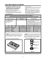
Страница 52: ...0 0 300 250 200 150 50 0 100 ALIGNMENT TAPES FOR ADJUSTMENT Derivation No Mechanism Adjustment ltems FM Envelope A PAL SP LP 2 4 Head TTV P2L B PAL SP 2 Head TTV P2 C NTSC SP LP EP 2 4 Head TTV N1 TTN...

Страница 53: ...Alignment is as below Fig C 2 4 Remove the Screw which fixes the Deck Mechanism and Main Frame and confirm if the Gear Cam is aligned with the Gear Drive as below Fig C 1 A 5 Confirm if the Mode S W o...

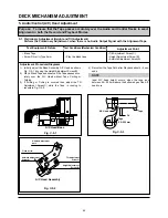
Страница 54: ...or with the Torque Gauge affixed The Torque reading to measure occurs when the Tape abruptly changes direction from Fast Forward of Rewind Mode when quick bracking is applied to both Reels SRK VIDEO C...

Страница 55: ...lope CH 2 NTSC SW 30Hz PAL SW 25Hz Head Switching Output Point RF Envelope Output Point Test ConditionsVCR VCP State Play an Alignment Tape Adjustment Point Guide Roller Height Adjustment Screws Fig C...

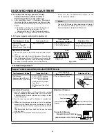
Страница 56: ...Screw Fig C 5 3 A C Head Tape Tape 0 2 0 25mm P4 5 1 Preliminary Adjustment Height and Tilt Adjustment Perform the Preliminary Adjustment when there is no Audio Output Signal with the Alignment Tape...

Страница 57: ...ent Screw C for Maximum Output of the 1Khz and 7Khz segments while maintaining the flattest Envelope differential between the two Frequencies Adjustment Procedure 5 3 Precise Adjustment Azimuth adjust...

Страница 58: ...echanism Condition Play the blank tape Play an alignment tape Adjustment Points Guide Roller Precise Adjustment Switching Point Tracking Preset X Value Checking Adjustment Procedure Play a blank tape...

Страница 59: ...rt on pinch roller If locations marked with o do not operate normally after clean ing check for wear and replace See the EXPLODED VIEWS at the end of this manual as well as the above illustrations See...

Страница 60: ...ch with Isopropyl Alcohol Touch the cleaning patch to the head tip and gently turn the head rotating cylinder right and left Do not move the cleaning patch vertically Make sure that only the buckskin...

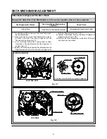
Страница 61: ...embly F L U Groove 4 Arm Take up Rubbing Section 5 L D Motor Worm Wheel Part 6 Shaft 7 Arm Assembly F L of Buming Inside Hole 8 Reel S T Shaft G381 Yellow 9 Brake T Groove Guide Rail Gear Assembly Up...

Страница 62: ...sensor Check syscon circuit YES YES YES NO NO NO 1 Deck Mechanism A NO NO NO No F R modes Is the present mode F R Mode Is the mode SW assembled correctly refer to Page 61 Is the normal voltage suppli...

Страница 63: ...tions page 61 Check spring Pinch Replace Drum Motor Check Servo Syscon Check the Syscon COM No cassette loading Insert the cassette Check Cassette Carry Assembly Is there variation for F L S W Output...

Страница 64: ...ors ok Check Syscon Circuit Check Syscon Circuit Check Servo Syscon Does the Capstan Motor turn Is the terminal voltage of the Drum Motor more than 2 3V Replace the Drum Motor Is the Vcc voltage of th...

Страница 65: ...ard 5V YES Is there a short circuit between cassette switch and GND on main P C Board Remove the short circuit part or Replace the main P C Board NO Check Mode switch location and syscon circuit Repla...

Страница 66: ...Assembly F L Check the power of L D Motor Is the Holder Assembly Cassette assembled correctly Replace the Rear Rack F L Does the Gear Rack F L work Does the Opener Door work Does the Arm Assembly F L...

Страница 67: ...920074 Printed in Singapore 2 11 IKENOHATA 1 CHOME TAITO KU TOKYO 110 8710 JAPAN TEL 03 3827 3111...

Отзывы: