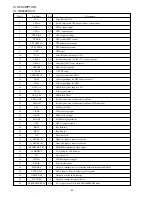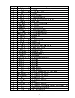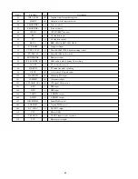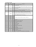
Pin No.
Pin Name
I/O
Description
55
43
44
45
46
47
48
49
50
51
52
53
54
55
56
57
58
59
60
61
62
63
64
65
66
67
68
69
70
71
72
73
74
75
76
77
78
79
80
81
82
83
R/C IN
S Canal
N.C
VCR 'H'
REC 'H'
OSD 'H'
T/UP REEL
CAP. REC 'H'
TOP SENSOR
SEARCH 'H'
PLUS2 DATA
R. FINDER
R/FIND MUTE 'L'
MAIN VCC
MAIN VSS
HSR 'H'
IIC CLK
IIC DATA
TIMER 'H'
P. CTL 'H'
FLD CLK
FLD DATA MS
FLD DATA SM
FLD ENA
STAND BY 'H'
MODE SW 4
MODE SW 3
MODE SW 2
MODE SW 1
LD (–)
LD (+)
FWE
X2 (32.768kHz/OUT)
X1 (32.768kHz/IN)
_______
RES
OSC1 (IN)
Vss
OSC2 (OUT)
VCL
MDO
D. ADJ
I
I/O
–
O
O
O
I
O
I
O
O
O
I/O
–
–
I/O
O
I/O
O
O
O
O
I
O
O
I
I
I
I
O
O
I
O
I
I
I
–
O
I
I
I/O
Remote input
C + & 2nd pass 16 : 9 detector
Not connected
TV/VCR control output
Recording current control output
OSD color control in YC SECAM/MESECAM mode
Take-up reel input
Capstan forward/reverse control output
Top sensor input
Capstan Vcc control output
VCR Plus+ II control code output
Remote control finder output control
Remote control finder muting control
Micom power supply
Micom GND
Capstan Vcc control output
IIC control clock pin
IIC control data pin
Power switch for VPS check during power off
VCR main power control output
FLD control clock output
FLD data output to Micom
Micom data input from FLD
FLD enable output
3W mode control output (FLD power off)
MD/SW4 input
MD/SW3 input
MD/SW2 input
MD/SW1 input
Loading motor drive (-)
Loading motor drive (+)
Flash memory write designation pin: Open for mask product
For the connection of 32.768 kHz OSC
For the connection of 32.768 kHz OSC
Micom reset pin (“L” active)
For the connection of 10 MHz OSC
Micom GND
For the connection of 10 MHz OSC
For the connection of capacitor to stabilize power supply (capacitor connected to Vss)
Designates advanced mode, coupled at “H”
Drum control output during slow


