background image

– 31 –

Содержание CX-ZL900

Страница 1: ...M Code No 09 004 424 5R1 R E V I S I O N Z L900 SPEAKER SYSTEM CD CASSEIVER SX WZL900 CX ZL900 REMOTE CONTROLLER RC ZAS12 This Service Manual is the Revision Publishing and replaces Simple Manual Z L900 LH S M Code No 09 001 424 5T1 If requiring information about the CD mechanism see Service Manual of 6ZG 1 ZRDM S M Code No 09 001 338 7N2 ...

Страница 2: ...ection Track format 4 tracks 2 channels stereo Frequency response CrO2 tape 50 Hz 16000 Hz Normal tape 50 Hz 15000 Hz Signal to noise ratio 50 dB CrO2 tape peak level above 400 Hz Recording system AC bias Heads Deck 1 Playback head x 1 Deck 2 Recording Playback head x 1 erase head x 1 Compact disc player section Laser Semiconductor laser λ 780 nm D A converter 1 bit dual Signal to noise ratio 85 d...

Страница 3: ...araten används på annat sätt än vad som specificeras i denna bruksanvising kan användaren utsättas för osynling laserstrålning som överskrider gränsen för laserklass 1 PROTECTION OF EYES FROM LASER BEAM DURING SERVICING CAUTION Use of controls or adjustments or performance of proce dures other than those specified herin may result in hazardous radiation exposure ATTENTION L utillisation de command...

Страница 4: ...in power 2 2 2 2 2 Confirm that the main power is turned on and the HOLD terminal of the MICROCOMPUTER keeps the H level or not 3 3 3 3 3 When the HOLD terminal is L level the abnormality detection circuit is judged to be working correctly and the MICROCOMPUTER is judged to be good 1 Forced discharge of electrolytic capacitor of power supply block When repair is going to be attempted in the set th...

Страница 5: ... ends of the electrolytic capacitor C113 that is connected to VDD of the MICROCOMPUTER with tweezers 3 3 3 3 3 Connect the AC power cord again If the MICROCOMPUTER returns to the normal operation the MICROCOMPUTER is good Note The reference number or MICROCOMPUTER pin number of transistor Q110 and electrolytic capacitor C113 can change depending on the models Be sure to check the reference numbers...

Страница 6: ...3 50 C27 87 016 300 080 CAP ELECT 22 100 C28 87 010 407 080 CAP ELECT 33 50 C31 87 010 263 080 CAP ELECT 100 10V C32 87 010 197 080 CAP CHIP 0 01 25 C34 87 010 247 080 CAP ELECT 100 50V C35 87 010 380 080 CAP ELECT 47 16V C36 87 010 381 080 CAP ELECT 330 16V C38 87 010 385 080 CAP ELECT 220 25V C39 87 010 385 080 CAP ELECT 220 25V C40 87 010 197 080 CAP CHIP 0 01 25 C60 87 010 403 080 CAP ELECT 3 ...

Страница 7: ...636 87 A10 307 080 CAP M S 0 1 50 C637 87 A10 307 080 CAP M S 0 1 50 C638 87 A10 307 080 CAP M S 0 1 50 C639 87 010 405 080 CAP ELECT 10 50V C643 87 010 196 080 C CAP S 0 1 25 ZF C644 87 010 401 080 CAP ELECT 1 50V C671 87 010 322 080 C CAP S 100P 50 CH C672 87 010 322 080 C CAP S 100P 50 CH C673 87 010 190 080 C CAP S 0 01 50 ZF C679 87 010 196 080 CHIP CAPACITOR 0 1 25 ZF C680 87 010 190 080 C C...

Страница 8: ...P E 4 7 50 5L C132 87 012 156 080 C CAP S 220P 50 CH C133 87 010 316 080 C CAP S 33P 50 CH C135 87 018 209 080 CAP TC U 0 01 50 C137 87 010 313 080 CAP CHIP 18P 50 C138 87 010 196 080 CHIP CAPACITOR 0 1 25 C171 87 010 213 080 C CAP S 0 015 50 B C172 87 010 183 080 C CAP S 2700P 50 B C188 87 010 194 080 CAP CHIP 0 047 25 C193 87 010 197 080 CAP CHIP 0 01 DM C251 87 010 196 080 CHIP CAPACITOR 0 1 25...

Страница 9: ...166 87 A00 418 010 RES M F 0 15 3W J R231 87 A00 669 080 RES M F 0 22 2W J R232 87 A00 669 080 RES M F 0 22 2W J R243 87 A00 669 080 RES M F 0 22 2W J R244 87 A00 669 080 RES M F 0 22 2W J TH101 87 A91 042 080 C THMS 100K 55001 TH102 87 A91 042 080 C THMS 100K 55001 WH101 87 A90 460 010 HLDR 2 5 7P CNTL C B C602 87 010 069 040 CAP E 0 33 50 C603 87 010 319 080 C CAP S 56P 50 CH C604 87 010 178 080...

Страница 10: ...1 50 Z F C11 87 A11 148 080 CAP TC U 0 1 50 Z F C12 87 A11 148 080 CAP TC U 0 1 50 Z F C101 87 010 387 080 CAP E 470 25 SME C103 87 A11 148 080 CAP TC U 0 1 50 Z F C104 87 A11 148 080 CAP TC U 0 1 50 Z F C105 87 A11 148 080 CAP TC U 0 1 50 Z F C106 87 A11 148 080 CAP TC U 0 1 50 Z F C107 87 A11 148 080 CAP TC U 0 1 50 Z F C108 87 A11 148 080 CAP TC U 0 1 50 Z F C109 87 A11 148 080 CAP TC U 0 1 50 ...

Страница 11: ...108 118 128 A A CHIP RESISTOR PART CODE 0 55 Resistor Code Dimensions mm Symbol 1 16W 1005 5 CJ 1 0 0 5 0 35 104 L t W TRANSISTOR ILLUSTRATION E C B CD1585 CSA952 CSC4115 KTA1266 KTC3198 KTC3199 E C B CC5551 2SB1370 2SB1588 2SD2439 2SA933 DTC114ES 2SB1237 E C B B C E 2SK3053 G D S E B C 2SA1235 2SC2714 2SC3052 2SD1306 CMBT5401 CMBT5551 E C B KRA102 KRA104 KRA107 KRC102 RT1P141C S G D 2SJ461 T1 2SK...

Страница 12: ...WIRING 1 MAIN VM 12 1 2 J603 2 2 10 11 12 13 14 15 16 17 18 19 20 21 22 23 24 A B C D E F G H I J K L M N O P Q R S T U 1 2 3 4 5 6 7 8 9 25 26 27 28 29 30 31 32 ...

Страница 13: ...SCHEMATIC DIAGRAM 1 MAIN 1 3 AMP SECTION VM 13 ...

Страница 14: ...SCHEMATIC DIAGRAM 2 MAIN 2 3 DECK SECTION HEAD 1 HEAD 2 14 ...

Страница 15: ...SCHEMATIC DIAGRAM 3 MAIN 3 3 TUNER SECTION 15 ...

Страница 16: ...WIRING 2 MICON 16 10 11 12 13 14 15 16 17 18 19 20 21 22 23 24 A B C D E F G H I J K L M N O P Q R S T U 1 2 3 4 5 6 7 8 9 25 26 27 28 29 30 31 32 ...

Страница 17: ...SCHEMATIC DIAGRAM 4 MICON DECK 17 ...

Страница 18: ...WIRING 3 CNTL 18 10 11 12 13 14 15 16 17 18 19 20 21 22 23 24 A B C D E F G H I J K L M N O P Q R S T U 1 2 3 4 5 6 7 8 9 25 26 27 28 29 30 31 32 ...

Страница 19: ...WIRING 4 MIC KEY CD DK1 LED DK2 LED 19 10 11 12 13 14 15 16 17 18 19 20 21 22 23 24 A B C D E F G H I J K L M N O P Q R S T U 1 2 3 4 5 6 7 8 9 25 26 27 28 29 30 31 32 ...

Страница 20: ...SCHEMATIC DIAGRAM 5 CNTL MIC KEY CD DK1 LED DK2 LED 20 ...

Страница 21: ...WIRING 5 AMP 1F 21 10 11 12 13 14 15 16 17 18 19 20 21 22 23 24 A B C D E F G H I J K L M N O P Q R S T U 1 2 3 4 5 6 7 8 9 25 26 27 28 29 30 31 32 ...

Страница 22: ...SCHEMATIC DIAGRAM 6 AMP 1F 22 ...

Страница 23: ...WIRING 6 PT 23 10 11 12 13 14 15 16 17 18 19 20 21 22 23 24 A B C D E F G H I J K L M N O P Q R S T U 1 2 3 4 5 6 7 8 9 25 26 27 28 29 30 31 32 ...

Страница 24: ...SCHEMATIC DIAGRAM 7 PT 24 ...

Страница 25: ...WIRING 7 DECK HEAD 1 HEAD 2 25 10 11 12 13 14 15 16 17 18 19 20 21 22 23 24 A B C D E F G H I J K L M N O P Q R S T U 1 2 3 4 5 6 7 8 9 25 26 27 28 29 30 31 32 ...

Страница 26: ...m analyser level detection 25 MIC I MIC input level detection 26 RDS SG I RDS Signal level input Not used 27 TM BASE I Time base clock input 28 CD WRQ RDS CLK I CD Read Write Request Tuner RDS clock input Not used 29 REM I Remote control signal input 30 42 G13 G1 O FL grid G13 G1 output 43 45 P38 P36 O FL segment P38 P36 output 46 VDD Power supply 47 P35 SPEANA A O FL segment P35 output Spectrum a...

Страница 27: ...ment P15 output Deck 2 auto stop input 69 P14 CAM1 O I FL segment P14 output Deck 1 CAM SW input L ON 70 P13 CST1 O I FL segment P13 output Deck 1 cassette detection SW L ON 71 P12 REA O I FL segment P12 output Deck 2 side A recordable SW L REC 72 VDD Power supply 73 83 P11 P1 O FL segment P11 P1 output 84 P39 O FL segment P39 output 85 KEYSCAN O KEYSCAN output L ON 86 MOTOR O DECK motor ON OFF co...

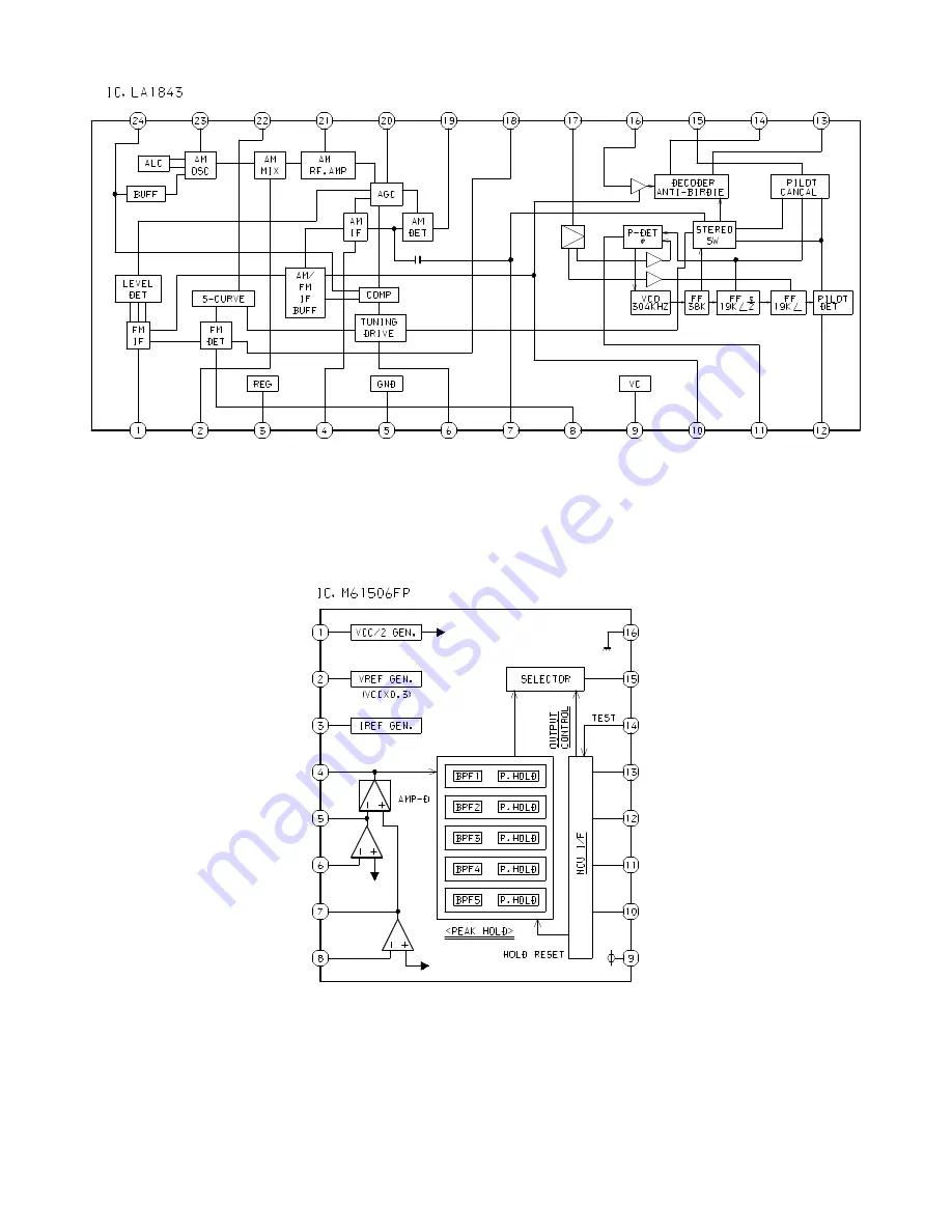
Страница 28: ... 28 IC BLOCK DIAGRAM ...

Страница 29: ... 29 ...

Страница 30: ... 30 ...

Страница 31: ... 31 ...

Страница 32: ... 32 ...

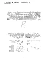
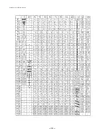
Страница 33: ... 33 FL BJ751GNK GRID ASSIGNMENT ANODE CONNECTION GRID ASSIGNMENT ...

Страница 34: ... 34 ANODE CONNECTION ...

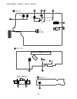
Страница 35: ...FR352 L801 TP2 CLK TP3 DC BALANCE GND TP9 RCH TP8 LCH 10 2 L802 7 4 TP1 VT 3 3 1 3 FFE831 O KSCAN 14 MICON C B B FL101 L101 SFR1 8 TP4 DC BALANCE 6 1 3 5 6 7 8 9 11 12 13 7 12 14 IC801 4 IC101 TP7 D GND DECK C B K DECK 1 P HEAD DECK 2 R P E HEAD REV FWD 9 9 ...

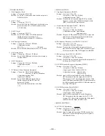
Страница 36: ...st point TP8 Lch TP9 Rch Adjustment location Head azimuth adjustment screw Method Play back FWD the 8kHz signal of the test tape and adjust screw so that the output becomes maximum Next perform on REV PLAY mode 10 PB Frequency Response Check DECK 1 DECK 2 Settings Test tape TTA 330 Test point TP8 Lch TP9 Rch Method Play back the 315Hz and 8kHz signals of the test tape and check that the output rat...

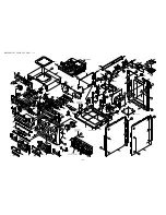
Страница 37: ... 37 MECHANICAL EXPLODED VIEW 1 1 ...

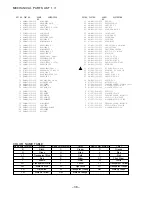
Страница 38: ...010 KEY TIMER 29 8A MA3 066 010 KEY FUN 5F 30 8A MA3 083 010 KEY ASSY DIR 31 8A MA3 072 010 KEY FREQ 32 8A MA3 073 010 KEY ENTER 33 8A MA3 074 010 KEY RHYTHM 34 8A MA3 084 010 KEY ASSY FF 35 8A MA3 069 010 KEY KARAOKE 36 8A MA3 057 010 WINDOW TOP 37 8A MA3 020 110 CABI TOP 38 8A MA3 101 010 REFLECTOR POWER 39 8A MA3 075 010 KEY POWER 40 88 MA1 205 010 GUIDE FL 41 8A MA3 061 010 KEY CD 42 8A MA3 10...

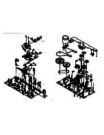
Страница 39: ... 20 5 22 21 24 23 25 26 29 29 27 28 3 2 HEAD 1 C B DECK 1 HEAD 2 C B DECK 2 18 DECK 2 PH DECK 1 RPH DECK 2 DECK 1 DECK 2 DECK 2 57 DECK 1 B B A B B 31 38 39 40 59 34 33 35 43 45 41 41 44 50 49 47 48 46 C C 54 53 55 DECK 1 D 56 52 51 D D 37 36 DECK C B SOL 2 SOL 1 50 A 8 8 A 58 32 C E ...

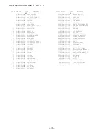
Страница 40: ...ZM1 255 319 SPR E LVR DIR 32 82 ZM3 305 01K GEAR CAM M2 33 82 ZM1 227 21K LVR TRIG 34 82 ZM3 306 11K LVR FR M2 35 82 ZM1 265 119 SPR E TRIG 36 82 ZM1 236 019 CAPSTAN N 2 41 5 37 82 ZM1 239 019 CAPSTAN N 2 2 41 7 38 82 ZM1 322 019 SPR T FR60 39 82 ZM1 220 219 GEAR IDLER 40 82 ZM3 616 019 RING MAGNET 4 41 82 ZM1 216 31K GEAR REEL 42 87 A90 366 010 HEAD PH YK50P BF414 FPC 42 87 A90 367 010 HEAD RPH Y...

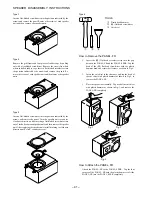
Страница 41: ...rning to clockwise direction until click sound comes out Remove the grill frame and four pieces of rubber caps by pulling out with a flat bladed screwdriver Remove the screws from hole where installed rubber caps Insert a flat bladed screwdriver into the position indicated by the arrows and remove the panel Re move the screws of each speaker unit and then remove the speaker units TOOLS 1 Plastic h...

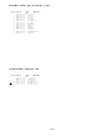
Страница 42: ... 8A MS3 010 010 PROTECTOR 7 8A MS2 001 010 PANEL FR 60 8 8A MS3 002 010 PANEL TW 9 8A MS3 003 010 PANEL BA 10 8A MS3 004 010 PLATE NAME 11 8A MS3 006 010 GRILLE FRAME ASSY 12 8A MS4 010 010 BADGE AIWA DESCRIPTION REF NO KANRI NO PART NO ACCESSORIES PACKAGE LIST 1 8A MA2 902 010 IB LH ESP M 2 8Z MA1 702 010 RC UNIT ZAS12 3 87 043 115 010 ANT FEEDER FM 4 87 A90 030 010 ANT LOOP AM NC C 5 87 099 789 ...

Страница 43: ...2 11 IKENOHATA 1 CHOME TAITO KU TOKYO 110 JAPAN TEL 03 3827 3111 Printed in Singapore 9420208 9630472 0251431 ...

Отзывы: