AITech Full HD Video Wireless Kit Скачать руководство пользователя страница 9


B.


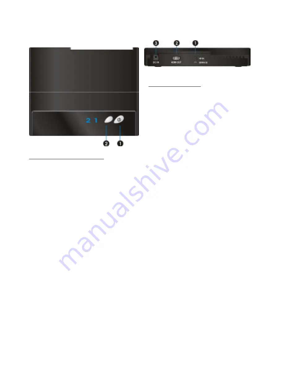
RECEIVER: Full HD Receiver 


    Front Panel Buttons and LEDs 


Power Button with LED indicator


Press to turn the receiver on and off.    The 
indicator in the power button lights up in blue 
when the power is on, and turns red in 
standby mode.     
 

 Source Selection Button


Press this button repeatedly until you see the 
desired video transmitted to your TV set.


 Main Unit Back Panel 


IR Sensor Extender Jack 

Plug the IR Sensor Extender cable into the IR IN 
jack at the rear panel of the receiver.


Generally, 

sensors with cable are placed near your HDTV 
set so that you can easily operate and control 
your AV equipment connected to 
TRANSMITTER by pointing the remote control 
to the TV instead of the AV equipment.     


HDMI OUT


For  connecting  the  HDTV  set  via  an  HDMI 
cable. 


DC IN 

For connecting the RECEIVER power adapter.   


Содержание Full HD Video Wireless Kit

Страница 1: ...0 Read Quick Guide and User Manual first for quick tips that make using your AITech product more enjoyable ProA V Media Extender Wireless HDMI AITech...

Страница 2: ...NT INFORMATION 2 SAFETY PRECAUTIONS 2 DANGER BE CAREFUL WITH ELECTRICITY 2 2 INTRODUCTION 6 2 1 PACKING CONTENT 6 2 2 OVERVIEW 7 3 INSTALLATION 12 4 TROUBLESHOOTING 24 5 SUPPORTED RESOLUTION 26 6 AUDI...

Страница 3: ...smitter and the receiver Power cord Be sure the power cord is routed so that it will not be stepped on or pinched by heavy items Power overloading Avoid overloading electrical outlets or extension cor...

Страница 4: ...nt up to and including 16 A per phase EN 61000 3 3 Electromagnetic compatibility EMC Part 3 Limits Section 3 Limitation of voltage changes voltage fluctuations and flicker in public low voltage supply...

Страница 5: ...is document supplied to an OEM or integrator but should not be distributed to the end user This device is intended for OEM integrators only Please See the full Grant of Equipment document for other re...

Страница 6: ...ure compliance Outdoor operations in the 5150 5250MHz 5600 5650MHz band are prohibited This device has no Ad hoc capability for 5250 5350MHz and 5470 5725MHz Outdoor operations in the 5470 5725MHz ban...

Страница 7: ...tent to your existing HDTV set wirelessly It operates the transmission in 4 9 GHz 5 9 GHz frequencies and it can adjust its communication frequency automatically in case of interference from another R...

Страница 8: ...R Blaster Extender Cable into the IR OUT jack at rear panel of the transmitter Attach the IR blaster to the device connected to the TRANSMITTER You can point your AV equipment s existing remote contro...

Страница 9: ...e the desired video transmitted to your TV set Main Unit Back Panel IR Sensor Extender Jack Plug the IR Sensor Extender cable into the IR IN jack at the rear panel of the receiver Generally sensors wi...

Страница 10: ...t at transmitter to enter Standby mode without Loop thru INFO Press to display between Channel Source Resolution WIDE mode and Signal Quality Press once to display the current status Press again to ex...

Страница 11: ...I1 CH10 WIDE Off 1280x1024 Standby Mode Loop thru On Press the INFO button on the RCU and Signal Quality Source Channel WIDE mode status and resolution will be displayed for user reference OSD Display...

Страница 12: ...of audio video contents 1 Press once for current WIDE mode status displayed on the OSD Default is disable HDMI1 CH10 WIDE Off 1280x1024 Press again to switch WIDE mode 2 Press WIDE button again withi...

Страница 13: ...e included The TRANSMITTER has two HDMI inputs for the latest High Definition device like PS3 Blu ray Player 2 Connect the TRANSMITTER s HDMI OUT to the HDTV set s HDMI IN port with an HDMI cable for...

Страница 14: ...o your HDTV set or an HD projector Press the Source Input button of your TV s remote to select the appropriate HDMI video input 2 Connect the supplied power adapter to the DC IN jack of the RECEIVER a...

Страница 15: ...sight 1 Plug the IR blaster cable into the IR OUT jack of the TRANSMITTER Place the IR blaster head near the IR sensor of your High Definition audio video devices nearby The infrared IR sensor should...

Страница 16: ...ols plug the IR Sensor Extender cable into the IR IN jack at the rear panel of the RECEIVER Note 1 The IR sensor supports 36KHz 56KHz NEC RC5 RC6 remote s signal protocol Therefore it is possible that...

Страница 17: ...lectrical outlet the ProA V Media Extender Wireless HDMI will be turned on automatically 3 If it is in Standby mode and Loop thru display off Both POWER LED of transmitter and receiver are lit in red...

Страница 18: ...CEIVER Note During this period TRANSMITTER will enter Standby mode and turn off Loop thru display when press the POWER button of transmitter or press the POWER key of RCU to transmitter 5 During the w...

Страница 19: ...Extender Wireless HDMI to different channels Note A Changing the ProA V Media Extender Wireless HDMI to a different wireless channel 1 Enter the wireless RF channel adjustment mode 2 Changes to the ne...

Страница 20: ...X X X X X US Non DFS Europe Non DFS Japan Non DFS WIDE mode ON Frequency MHz Support Region Channel Support Region Channel Support Region Channel 5160 X X X X X X 5180 V 1 V 1 V 1 5200 V 2 V 2 V 2 522...

Страница 21: ...mption Loop through display always on Please refer Section 2 2 paragraph C D for detailed description Static Red Off Standby For very lower power saving EuP used Please refer Section 2 2 paragraph C D...

Страница 22: ...n line of sight LOS scenarios The minimum range is 6 5 feet B If the connection or link is lost it may be caused by the following reasons a The range is over the maximum transmission distance b Either...

Страница 23: ...n on the remote control to enable the Wide mode for longer range audio video transmission Note Only 1080i or below HD video transmission is available when enabling the Wide mode OSD shows WIDE On Plea...

Страница 24: ...holes and attach this paper on wall 2 Drill pilot holes 3 Insert the supplied two Anchors into the wall 4 Insert two screws into the anchors Leave 1 8 length for mounting the Transmitter or receiver 5...

Страница 25: ...Move the transmitter closer to the receiver Press CHANNEL on the included remote control to manually change the wireless channel POWER LED in Solid Blue Slow and Flashing SOURCE LED Ensure your video...

Страница 26: ...k Charpter5 Supported resolution Some resolution can t support on WIDE mode on IR Blaster can t control Source device Check where is IR sensor of Source device Make sure IR Blaster sensor is close and...

Страница 27: ...CEA Video Timing 640x480p 59 94 60Hz YES YES 720x480p 59 94Hz YES YES 720x480p 60Hz 480p YES YES 720x576p 50Hz 576p YES YES 1280x720p 50Hz YES YES 1280x720p 59 94 60Hz 720p YES YES 1920x1080i 50Hz YE...

Страница 28: ...udio from HDMI inputs Up to 6Mbit s bit rate support Support AC3 and DTS 2 channel PCM over S PDIF 16 24 bits audio sample with 32 48KHz sampling rate 2channel PCM 32KHz 44 1KHz 48KHz 96KHz 16 bits YE...

Страница 29: ...00 240V AC in 5V 3A DC out Power Adaptor Operating Temperature 0 40 C Interfaces TRANSMITTERT RECEIVER HDMI Input TWO Type A A V Interfaces HDMI Output One Loop through One Type A IR Sensor YES IR Sen...

Страница 30: ...29...

Страница 31: ...30...

Отзывы: