background image

5

Split system gainable à pression - 

Ductable pressurized split system - 

Split-system für Kanalanschluß unter Druck

Mit den 3 Ventilatordrehzahlen des
Innenteils CD kann die Luftmenge je
nach Druckverlust in den Kanälen
geregelt werden.

Im Automatikbetrieb wird die Drehzahl
je nach der Momentananforderung
gewählt.

Un petit récepteur à infrarouge mural situé
dans la zone voulue permet, par l’intermé-
diaire de la commande infrarouge, de sé-
lectionner toutes les fonctions du climati-
seur.

A small wall-mounted infrared receiver
located where desired to allow remote
control of all the functions.

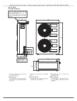
EXEMPLE D’INSTALLATION

- Equipement partagé avec distribution d’air

par gaines et reprise par grille dans faux pla-
fond.

- Unité extérieure GC  placée sur une terrasse

supérieure.

- Unité intérieure CD placée dans un faux pla-

fond.

- Différence de hauteur max. entre les deux

unités (voir tableau page 18).

- Connexion entre les deux unités par 2

liasons frigorifiques (voir page 18/19).

Sans ajout de réfrigérant :

Le CD 35 peut être installé sur une longueur de 15m max.
Le CD 43 et 50 sur une longueur entre 8 et 28m.
Le CD 60 sur une longueur entre 8 et 30m.

Without addition of refrigerant:

CD 35 can be installed over a maximum length of 15 m.
CD 43 and CD 50 can be installed over a length between 8
and 28 m.
CD 60 can be installed over a length between 8 and 30m.

Les 3 vitesses du ventilateur de l’unité
intérieure CD permettent de régler le
débit en fonction de la perte de charge
des gaines.

The three fan speeds of the CD indoor
unit allow the air flow rate to be
adjusted according to the pressure
loss in the ducts.

Pour l’équipement GC35, la charge
d’origine permet un fonctionnement
jusqu’à 15 m sans ajout de frigori-
gène.
Pour des longueurs supérieures, une
quantité définie doit être ajoutée. Voir
page 19.

DESCRIPTION

Généralités

Terminal de télécommande à infrarouge

- Les climatiseurs comportent un système de

commande par microprocesseur avec pro-
grammes de fonctionnement automatique et
télécommande à infrarouge exclusive.

DESCRIPTION

General

Infrared Remote Control Unit

- Split systems include an exclusive

microprocessor control system with
automatic programs and infrared remote
control units.

EXAMPLE OF INSTALLATION

- Split system with air distribution through

ducts and recovery through grating in dou-
ble ceiling

- GC outdoor unit located at a height on a

terrace

- CD indoor unit located in a double ceiling
- Maximum difference in height between the

two units (table page 18).

- Two units interconnected by two refrigerant

lines (see page 18/19)

BESCHREIBUNG

Allgemeines

Infrarot-Fernbedienung

- Die Klimageräte verfügen über eine

Mikroprozessor-Steuerung mit
automatischen Betriebsprogrammen und
exklusiver Infrarot-Fernbedienung.

INSTALLATIONSBEISPIEL

- Split-System mit Kanal-Luftverteilung und

Ansaug über Gitter in Zwischendecke.

- Außenteil GC auf Terrassendach.
- Innenteil CD in Zwischendecke.
- Maximaler Höhenunterschied zwischen den

beiden Teilen (siehe Tabelle Seite 18).

- Verbindung der beiden Einheiten durch 2

Kältemittelleitungen (siehe Seite 18/19).

The original charge of the CG35 unit
allows operation up to 15 m without
additional refrigerant.
Refrigerant must be added for longer
distances.  For quantities, see page
19.

Bei dem GC35 ist mit der ursprünglichen
Ladung ein Betrieb bis 15 m ohne Zusatz von
Kältemittel möglich.
Bei größeren Längen muß Kältemittel
hinzugefügt werden; genaue Mengen siehe
Seite 19.

En kleiner Infrarotempfänger für
Wandmontage in der gewünschten Zone
ermöglicht über eine Infrarotsteuerung, alle
Funktionen des Klimageräts anzuwählen.

Ohne Zusatz von Kältemittel:

Der CD 35 kann über eine Länge von maximal 15 m
installiert werden.
Der CD 43 und 50 kann über eine Länge zwischen 8 und
28 m installiert werden.
Der CD 60 kann über eine Länge zwischen 8 und 30 m
installiert werden.

Содержание CD17

Страница 1: ...sezt Annulla e sostituisce anula y sustituye TH2722 L Split system gainable pression Ductable pressurized Split system Split system f r Kanalanschlu unter Druck Condizionatore Split System con distrib...

Страница 2: ......
Страница 3: ...NOTICE D INSTALLATION INSTALLATION INSTRUCTION INSTALLATIONSHANDBUCH ISTRUZIONI INSTALLAZIONE INSTRUCCIONES DE INSTALACI N INSTALLATIE HANDLEIDING...

Страница 4: ...nd the current required for any other appliance connected with the same circuit WARNING Cutoff power supply before starting to work on the appliance The manufacturer declines any responsibility and th...

Страница 5: ...TIONNEMENT Maintenance 27 SUMMARY DESCRIPTION General 5 6 General Specifications 7 8 Dimensions of Indoor Units 9 12 Dimensions of Outdoor Units 13 15 INSTALLATION Location of the Outdoor Unit 16 Loca...

Страница 6: ...l b i s u f e r b i l a C r u e t c n o j s i d e r b i l a C e l b c e d n o i t c e S s n o s i a i L e l b c e d n o i t c e S d r a d n a t S s a C e l b i s r e v R s a C A A A A m m m m 7 1 0 2...

Страница 7: ...TION G n ralit s Terminal de t l commande infrarouge Les climatiseurs comportent un syst me de commande par microprocesseur avec pro grammes de fonctionnement automatique et t l commande infrarouge ex...

Страница 8: ...re d port en rallongant les fils moteur et les fils de sonde Les moteurs des ventilateurs des climati seurs CD ont 3 vitesses ce qui permet un r glage du d bit selon les pertes de charge des conduites...

Страница 9: ...1 6 2 y t i c a p a c g n i t a e h l a n i m o N t u p n i r e w o p l a t o T 2 g n u t s i e l z i e h n n e N t m a s e g s n i e m h a n f u a s g n u t i e L e r d n a l a C s i n a v l a g r e...

Страница 10: ...e v O t h g i e H h t d i W h t p e D n e g n u s s e m b A e n i e m e g l l A e h H e t i e r B e f e i T t e n s d i o P g k 3 6 3 6 7 6 7 8 5 9 0 2 1 4 2 1 t h g i e w t e N t h c i w e g o t t e...

Страница 11: ...NIT S INT RIEURES CD CD17 CD22 CD26 DIMENSIONS OF CD INDOOR UNITS CD22 Raccord Flare 5 8 et 3 8 Flare coupling 5 8 and 3 8 B relanschl sse 5 8 und 3 8 ABMESSUNGEN DER INNENTEILE CD17 CD22 Sortie des t...

Страница 12: ...25 50 225 225 50 25 210 340 586 930 110 350 850 900 140 90 20 60 327 720 25 20 745 290 CD35 CD43 Sortie des tubes Exit pipes Rohraustritt Coffret lectrique Terminal box Schaltschrank Sortie des tubes...

Страница 13: ...1410 180 25 290 225 225 290 25 210 340 586 1380 110 350 1300 1350 140 90 20 60 327 720 25 20 745 290 Use 7 8 pipe for the suction line GC50 CD50 units The connections are 3 4 as per standard RWT V Aft...

Страница 14: ...t ressouder les tubes dans la configuration d sir e 1425 25 242 302 302 242 25 256 400 400 1400 1300 1350 23 5 250 640 25 25 22 5 350 83 25 25 30 28 28 700 151 45 75 120 30 A The tubes coolant and con...

Страница 15: ...iques GC35 3 4 et 3 8 Service valve for connection of refrigerant lines GC35 3 4 and 3 8 Vannes de service pour raccordement des tubes frigorifiques pour tube vas GC17 3 8 et 1 2 GC22 3 8 et 5 8 GC26...

Страница 16: ...tation lectrique par le couvercle lat ral Power supply cable inlet through the side Vannes de service pour raccordement des tubes frigorifiques GC43 3 4 et 3 8 Eintritt der Speisekabel durch die seitl...

Страница 17: ...ifiques GC50 3 4 et 1 2 GC60 7 8 et 5 8 Fourniture de 2 tubes 7 8 dudgeonn s avec crous pour raccordements de la ligne GAZ Prise de pression Pressure tapes Eintritt der Speisekabel durch die seitliche...

Страница 18: ...d o M l l e d o M l l e d o M a m i n i m s e c n a t s i D a m i n i m s e c n a t s i D a m i n i m s e c n a t s i D a m i n i m s e c n a t s i D a m i n i m s e c n a t s i D e c n a r a e l c m...

Страница 19: ...ndensate evacuation tray as follows 1 and 2 remove the access panels 3 remove the screws securing the evaporator and the condensate evacuation tray 4 remove the condensate evacuation tray from the uni...

Страница 20: ...the double ceiling As shown in the drawing a siphon is to be made on site minimum 30 mm on the condensate drain line to ensure condensate drainage during operation of the indoor fan If there is not s...

Страница 21: ...at a significant height difference without a si phon see table on page 18 2 For the GC17 GC22 and GC26 models fit a siphon on the Gas line every 3m if the vertical section exceeds 8m for maxi mum heig...

Страница 22: ...u p t a e H d n a y l n o g n i l o o C p m u p t a e H d n a y l n o g n i l o o C p m u p t a e H d n a y l n o g n i l o o C P W d n u d r a d n a t S P W d n u d r a d n a t S P W d n u d r a d n...

Страница 23: ...2 1 8 7 8 5 8 7 S E L E D O M S E L E D O M S E L E D O M S E L E D O M S E L E D O M L E D O M L E D O M L E D O M L E D O M L E D O M E L L E D O M E L L E D O M E L L E D O M E L L E D O M E L L E...

Страница 24: ...sealed Use an electronic leak detector or a soapy sponge ENTLEEREN DER K LTEMITTELLEITUNGEN UND DES AU ENTEILS Nur das Au enteil ist mit R22 geladen Das Innenteil enth lt eine kleine Menge Neutralgas...

Страница 25: ...acer par la prise de configuration rep ELD RC fournie avec l ap pareil The ST is configured for COOLING ONLY To configure it for HEATPUMP remove con figuration plug P N ELD ST and replace it with conf...

Страница 26: ...mp Power supply via the indoor unit Sectionneur NON fourni SectionswitchNOTsupplied TrennschalterNICHTgeliefert Stromversorgung der Ger te Schaltung Modelle GC17 22 26 CD Klimager t ohne W rmepumpe un...

Страница 27: ...ittunten Modelle GC35 43 50 60 CD Klimager t ohne W rmepumpe und mit W rmepumpe Versorgung ber das Au enteil Sectionneur NON fourni SectionswitchNOTsupplied TrennschalterNICHTgeliefert Unit int rieure...

Страница 28: ...ANDE R CEPTEUR INFRAROUGE CONTROL PANEL INFRARED RECEIVER INTERCONNECTION A 7m shielded cable with connectors at both ends is provided with the equipment for interconnecting the control panel and infr...

Страница 29: ...s pouvant nuire l isolation V rifier que les c bles d interconnexion en tre les deux unit s ne pr sentent pas d al t rations et sont connectement raccord s Resserrage si besoin V rifier le raccordemen...

Страница 30: ...28 Split system con distribuzione aria a pressione Split System con conexion a conductos a presion Split systeem voor luchtkoker aansluiting...

Страница 31: ...SION DBT 73 23 CEE ENMENDATA POR LA DIRECTIVA 93 68 CEE DIRECTIVA COMPATIBILIDAD ELECTROMAGNETICA 89 336 CEE DIRECTIVA DE LOS EQUIPOS A PRESION DESP 97 23 CEE MODULO A CATEGORIA I D claration CE de co...

Страница 32: ...non danno luogo ad alcun vincolo contrattuale Con objeto de mejorar constantemente nuestros productos pueden ser modificados sin previo aviso Fotos no contractuales A C E Marketing France 1 bis Avenue...

Отзывы: