background image

Quick In stallation  & Co nfigu ration  Gu id e 

AS W i p LL 900 MHz 

32 

Airspan Networks Inc. 

13070311-02 


3. In the 

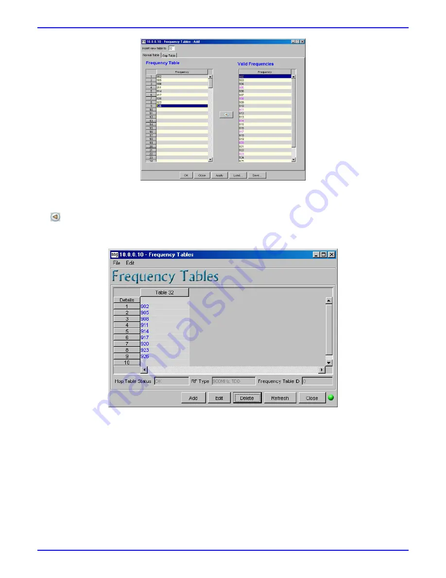
Insert New Table to

 field, enter the frequency table’s index number (32 to 63). If you do not enter a 

number, WipManage automatically assigns it the next available consecutive frequency table index number. 

4.  Add each frequency by selecting each frequency In the 

Valid Frequencies

 pane, and then clicking the left 

 arrow to add the frequency to the 

Frequency Table

 pane (i.e. left pane). 

5. Click 

OK

; The Frequency Tables Add dialog box closes, and the added frequency table appears in the 

Frequency Tables dialog box, as displayed below. 


13.2. Copying BSR Frequency Table to SPRs/IDRs 

The BSR and the SPRs/IDRs must use the 

same

 frequency table (i.e. same frequency table index and 

comprised of the same frequencies). After you have defined the NVRAM Frequency Table for the BSR, you 
need to simply copy the BSR's frequency table to all the SPRs/IDRs. This is performed in the BSR Zoom 
window's MultiDevices menu. 

To copy the BSR's NVRAM Frequency table to associated SPRs/IDRs (using WipManage): 

1.  In the BSR Zoom window, from the MultiDevices menu, point to 

RF

, and then choose 

Frequency Tables

The Multi SPRs Frequency Tables dialog box appears. 

2. Click 

Refresh

 to ensure that recently added BSR frequency tables have been updated. 

3.  Select all the SPRs/IDRs (for which you want to communicate with the BSR) by clicking the 

Select All

.  

Содержание ASWipLL

Страница 1: ...ASWipLL 900 MHz Wireless IP Based Local Loop System Quick Installation Configuration Guide Leading the World in Wireless DSL ...

Страница 2: ...ormation contained herein may be published reproduced or disclosed to third parties in whole or in part without the express prior written permission of Airspan Networks Inc In addition any use of this document or the information contained herein for any purposes other than those for which it was disclosed is strictly forbidden Airspan Networks Inc reserves the right without prior notice or liabili...

Страница 3: ...cation cabling including antennas Do not connect and disconnect antennas while power is on Inherent risks exist in operating equipment in license exempt bands i e 900 MHz Airspan recommends that you do not purchase or deploy any equipment that operates in license exempt bands without first analyzing the interference environment at each of your proposed deployment locations Please contact your Auth...

Страница 4: ...PR IDR Initialization 22 Analyzing the RF Spectrum 23 9 1 Accessing the Spectrum Analyzer 23 9 2 Setting up the Spectrum Analyzer 23 9 3 Starting the Spectrum Analyzer 24 9 4 Viewing Results 24 9 5 Quitting the Spectrum Analyzer 24 Configuring PC s IP Address 25 Establishing Link using WipManage 26 11 1 Adding a BS Group 26 11 2 Adding a BS 26 11 3 Adding a BSR 27 11 4 Adding an SPR IDR 27 11 5 Te...

Страница 5: ...or detailed descriptions Airspan recommends that you refer to the following ASWipLL books Hardware Installation Guide describes mounting and cabling ASWipLL devices WipConfig User s Guide describes initial configuration using WipConfig WipManage User s Guide describes using the WipManage network management tool Commissioning Manual provides step by step instructions on configuring the ASWipLL syst...

Страница 6: ...odels BSR with an integral antenna BSR 900 MHz TDD V pol BSR with two N type ports displayed below for attaching up to two external antennas BSR 900 MHz TDD Dual Ext 1 2 SPR The SPR is an encased CPE outdoor radio module providing access to a 15 pin D type port for Ethernet serial and power interfaces The SPR model is available in two models SPR with an integral antenna SPRL 900MHz TDD V pol and S...

Страница 7: ...s For IDR antenna alignment the IDR provides LEDs that indicate received signal strength RSS These LEDs are described in the table below LED Color Status RSS level ASWipLL Release 4 2B and later All LEDs on RSSI 60 dBm Two LEDs LO MED on 70 dBm RSSI 60 dBm One LED LO on 80 dBm RSSI 70 dBm One LED LO blinking 90 dBm RSSI 80 dBm RSSI LEDs LO MED HI Green All LEDs off RSSI 90 dBm TNC type connector f...

Страница 8: ...nt When you install at the rear the front of the building blocks incoming signals from multipath reflections Clean frequencies selected from Spectrum Analyzer results see Chapters 9 and 13 Maximum received signal strength RSS at CPE by antenna alignment For the IDR RSS can be measured by the IDR s built in RSS LEDs for the SPR RSS can be measured by Airspan s WipConfig program or by connecting Air...

Страница 9: ...o directional antennas Higher sensitivity to external interferences Higher sensitivity to multipath resulting in the following The root mean square RMS delay spread at the Base Station is substantially higher Multipath interference at the CPE side when using omni directional antenna at the Base Station is substantially higher In fact when using an omni directional antenna the existence of clear Fr...

Страница 10: ... 4 dB cable loss To define BSR transmit power taking into consideration cable loss using WipManage 1 In the BSR Zoom window from the Configuration menu point to RF and then choose Power Settings 2 Ensure the Power Management Mode Active check box is cleared On the Power Level slide ruler define the BSR s maximum power level e g 23 dBm 3 In the Loss Compensation field enter the power to compensate ...

Страница 11: ...teel bolts 2 Attach the clamping bracket to the mounting bracket using two M8 stainless steel bolts 3 Attach the Clamping bracket to the pole by placing the two U bolts around the pole and then inserting the U bolt through the Clamping bracket and securing it by screwing the two bolts on the U bolt 4 Adjust the vertical position of the BSR SPR Lock the BSR SPR at the desired position by inserting ...

Страница 12: ...ket s four holes with the wall anchors and then insert a screw through the mounting bracket holes into each wall anchor and secure by tightening Note Airspan does not provide screws for attaching the mounting bracket to the wall The screw size depends on the structure of the building to which the bracket is to be attached When selecting screw sizes consideration must be given to the weight of the ...

Страница 13: ...r pinouts Straight through CAT 5 UTP PVC 4Pair 24 AWG cables BSR BSDU SDA 15 pin D type male Pin Function Wire color Wire pair Pin Function 15 pin D type male 1 48 VDC Blue White 1 48 VDC 2 48 RTN Blue 1 2 48 RTN 3 Tx Orange White 3 Rx 4 Tx Orange 2 4 Rx 5 Rx Green White 5 Tx 6 Rx Green 3 6 Tx 7 Sync Brown White 7 Sync 8 Sync Brown 4 8 Sync Cable connection 1 Connect the 15 pin D type male connect...

Страница 14: ...UTP PVC 4Pair 24 AWG cables SPR SDA 15 pin D type male Pin Function Wire color Wire pair Pin Function 15 pin D type male 1 48 VDC Blue White 1 48 VDC 2 48 RTN Blue 1 2 48 RTN 3 Tx Orange White 3 Rx 4 Tx Orange 2 4 Rx 5 Rx Green White 5 Tx 6 Rx Green 3 6 Tx Cable connection 1 Connect the 15 pin D type male connector at one end of the CAT 5 cable to the SPR s 15 pin port 2 Connect the 15 pin D type ...

Страница 15: ...SR must remain connected to the BSDU SDA Connector pinouts Crossover cable BSR PC 9 pin D type male Pin Function Pin Function 9 pin D type female 2 RS232 Rx 3 Tx 3 RS232 Tx 2 Rx 5 GND 5 GND Cable connection 1 Connect the 9 pin D type male connector at one end of the serial cable to the BSR s serial port labeled Serial 2 Connect the 9 pin D type female connector at the other end of the serial cable...

Страница 16: ...type male 1 48 VDC 1 48 VDC 2 48 RTN 2 48 RTN 3 Ethernet Tx 3 Rx 4 Ethernet Tx 4 Rx 5 Ethernet Rx 5 Tx 6 Ethernet Rx 6 Tx SPR PC Pin Function Pin Function 9 pin D type female 12 GND 5 GND 14 RS232 Rx 3 Rx 15 RS232 Tx 2 Tx Cable connection 1 Connect the 15 pin D type male connector at the one end of the Y cable to the SPR 2 Connect the 15 pin D type male connector at the other end of the Y cable to...

Страница 17: ...RJ 11 port to the PC s serial port Connector pinouts Crossover cable IDR PC 6 pin RJ 11 Pin Function Pin Function 9 pin D type female 1 Rx 3 Tx 5 GND 5 GND 6 Tx 2 Rx Cable connection 1 Connect the 6 pin RJ 11 connector at one end of the crossover cable to the IDR s RJ 11 port labeled Serial 2 Connect the 9 pin D type female connector at the other end of the crossover cable to the PC s serial port ...

Страница 18: ...Software requirements operating systems Microsoft Windows NT 4 work station English only SP 3 0 or higher Microsoft Windows 2000 Professional Microsoft Windows XP Professional 7 1 Installing WipConfig The WipConfig program is supplied on a CD ROM To install WipConfig 1 Insert the WipConfig CD in your CD ROM drive 2 On the Windows taskbar click Start and then choose Run 3 Type D WIPCONFIG EXE where...

Страница 19: ...ot installed on your PC select the Add MS Access ODBC Drivers check box 9 Select the Add Data Source check box if you are performing a first time installation of WipManage and then click Next 10 Enter the Customer Key to continue the installation alternatively leave the Customer Key field empty and then click Next to continue 11 Click Next to begin installing WipManage If you selected the Add Data...

Страница 20: ...in bridge mode ensure IP addressing scheme enables IP connectivity between PC and devices 2 For establishing a link in router mode refer to the ASWipLL Commissioning Manual 8 1 Default Settings Airspan s factory default settings for the ASWipLL devices are listed in the following table Parameter Default value IP address BSR SPR IDR BSDU 10 0 0 10 10 0 0 20 10 0 0 5 Subnet mask BSR SPR IDR and BSDU...

Страница 21: ...Address enter the BSR s Air MAC address 0x0000 through 0xFFFF e g 0x1200 Notes 1 For the Air MAC address Airspan recommends using only the most significant bytes MSB e g the two left most bytes and not the least significant bytes LSB e g the right most bytes For example a typical Air MAC address would be AB00 where the zeros represent the LSB 2 To ensure each BSR has a unique Air MAC address ensur...

Страница 22: ...he Bridge Mode drop down list select Bridge i e transparent bridge mode 6 In the Network Configuration group enter the following fields Eth IP Address enter the SPR s IDR s IP address e g 10 0 0 20 Eth Subnet Mask enter the SPR s IDR s subnet address e g 255 255 255 0 Default Gateway enter the SPR s IDR s default gateway s IP address if relevant 7 In the RF Configuration group enter the following ...

Страница 23: ...lear area from this initial sweep run another batch of sweeps concentrating on these selected frequencies The fewer frequencies the more reliable the analysis for capturing bursty intermittent transmitters e g pagers 6 When using external antenna ensure correct Antenna Gain is defined with consideration to RF cable loss 7 As interference depends on geographical locations it is recommended to perfo...

Страница 24: ... Spectrum Analyzer To start and stop the Spectrum Analyzer click the Start and Stop buttons located below the graph respectively 9 4 Viewing Results The Spectrum Analyzer results are plotted on the graph as well as displayed in the Results table to access the Results table simply click the Results tab The following measurements are displayed Average received signal strength RSS per frequency plott...

Страница 25: ... click My Network Places and then from the shortcut menu choose Properties The Network and Dial up Connections folder appears 2 Right click the desired connection and then from the shortcut menu choose Properties The Local Area Connection Properties dialog box appears 3 In the Components list select Internet Protocol TCP IP and then click Properties The Internet Protocol TCP IP Properties dialog b...

Страница 26: ...Tree right click and then from the shortcut menu choose Add BS Group The BS Group Add dialog box appears 2 In the Group Name field enter a name for the BS Group e g Manhattan_1 and then click OK 11 2 Adding a BS You can now add a Base Station BS to the BS Group you added in the previous subsection To add a BS 1 In the Database Tree click the e g Manahattan_1 branch to which you want to add the BS ...

Страница 27: ...row as the BSDU to which you want to add the BSR and then from the shortcut menu choose Add BSR The BSR Add dialog box appears 3 In the Manage IP field enter the BSR s IP address e g 10 0 0 10 4 In the Get Community and Set Community fields enter the SNMP community rights 5 Click OK Double click the BSR icon to access the BSR Zoom window 11 4 Adding an SPR IDR After you have added a BSR you can ad...

Страница 28: ...dures i e Route button 2 For establishing a link in router mode refer to the ASWipLL Commissioning Manual 3 Click OK The SPR index 2 icon appears green as shown below indicating that a viable air and network link exists with the SPR IDR You can now manage the SPR IDR 11 5 Testing BSR SPR IDR Network Link You can test the BSR SPR IDR link by pinging the SPR IDR from a PC located behind the BSR To t...

Страница 29: ...e i e BSR BSDU and SPR IDR You can also define the trap SNMP community string that you want the management station to receive This is relevant only for third party SNMP external management stations e g HP OpenView WipManage management stations receive traps regardless of community string To define a management station for receiving traps e g for the BSR 1 In the BSR Zoom window from the Configurat...

Страница 30: ... OK Notes 1 Traps are displayed with a specific severity level Normal Warning Major and Critical 2 To show the Traps pane in the WipManage main window from the View menu choose Traps Pane 3 To receive traps ensure the Stop Listening button is displayed default on the WipManage main window s toolbar If the Start Listening button is displayed click this button 4 Traps that are saved in the DB appear...

Страница 31: ...mum separation of 4 MHz between these adjacent BSRs In addition when operating in the ISM band it is recommended to use as many frequencies as possible to increase immunity to random interference Airspan allows you to define up to 32 NVRAM frequency tables using WipManage These frequency tables can consist of multiple frequencies for frequency hopping based wireless communication These NVRAM frequ...

Страница 32: ...x as displayed below 13 2 Copying BSR Frequency Table to SPRs IDRs The BSR and the SPRs IDRs must use the same frequency table i e same frequency table index and comprised of the same frequencies After you have defined the NVRAM Frequency Table for the BSR you need to simply copy the BSR s frequency table to all the SPRs IDRs This is performed in the BSR Zoom window s MultiDevices menu To copy the...

Страница 33: ...table This is performed by instructing the BSR which frequency table to use To select the frequency table ID using WipManage 1 In the BSR Zoom window from the Configuration menu point to RF and then choose Hopping Configuration The Hopping Configuration dialog box appears 2 In the Frequency Table ID field enter the ID number of the frequency table that you added to the BSR and SPRs IDRs i e 32 Not...

Страница 34: ...TP sessions to an FTP server that is physically connected to the BSR s LAN port e g Microsoft IIS and Linux FTP built in servers The few concurrent sessions eliminate the Slow Start phenomenon succinct explanation can be found in RFC 2001 During the test record the RSS and BER levels for the BSR and SPR IDR This information is useful to Airspan s technical support team for future diagnosis Using t...

Страница 35: ...s defined correctly e g if the index was defined as 2 in WipConfig then in WipManage add the SPR IDR to index icon 2 Ensure that the external antenna is connected if an external antenna exists Ensure that the distance between the BSR and SPR IDR is in range for RF communication Ensure that no obstacles e g buildings between BSR and SPR IDR that may block transmission path 15 3 No PC SPR IDR Networ...

Страница 36: ...bridge House Oxford Road Uxbridge Middlesex UB8 1UN United Kingdom Tel 44 895 467100 Headquarters Airspan Networks Inc 777 Yamato Road Suite 105 Boca Raton FL 33431 USA Tel 1 561 893 8670 Fax 1 561 893 8671 Airspan Networks Web site http www Airspan com Cat No 73000006 ...

Отзывы: