background image

E st abli shing   BS R - SP R  L in k w ith  Au to Co nn ect 

C o m m i ssi o n i n g   M an u al  


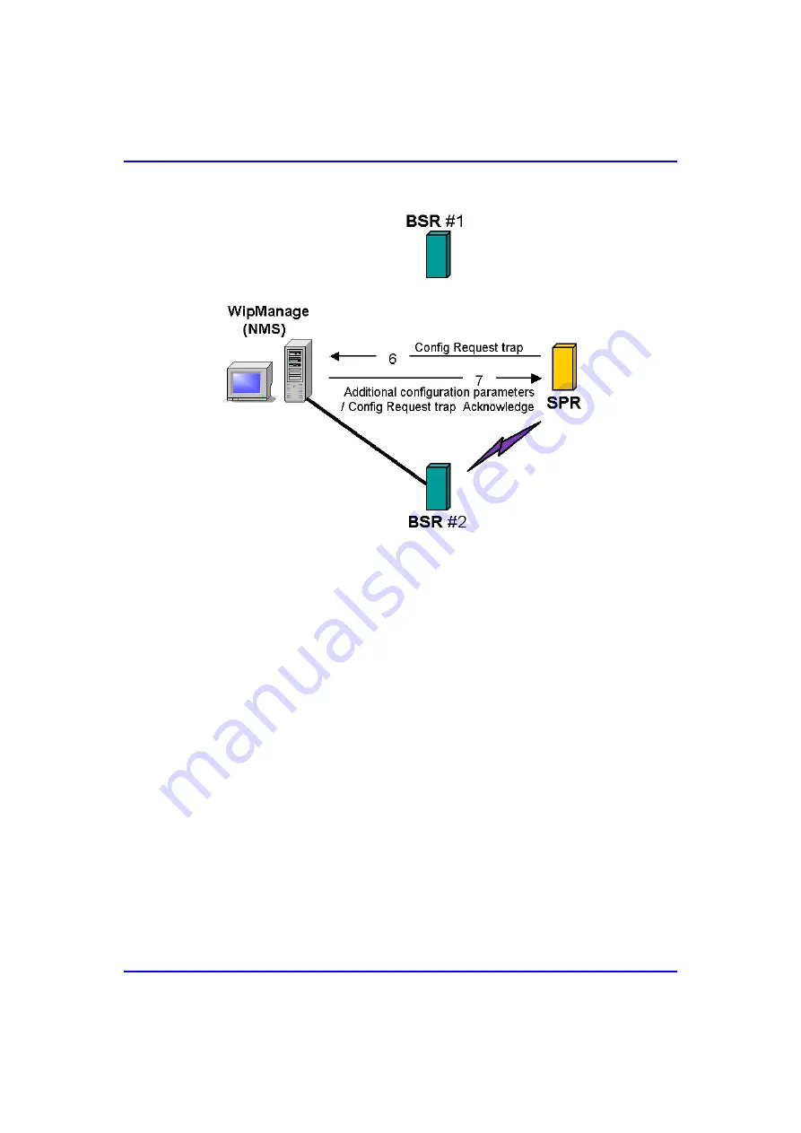
Figure 


8-3:  AutoConnect after Redirecting SPR to a different BSR 

The following lists the chronological process of the AutoConnect feature with 
redirecting SPRs to a different BSR: 

1. 

2. 

3. 

4. 

Once an unconfigured SPR is installed at the subscriber’s site, and then turned 
on, it automatically establishes a link with the BSR (

BSR #1

) with the strongest 

reception. 

The BSR (

BSR #1

) provides the SPR with a temporary IP address (for 

communication and configuration). 

The SPR sends an SNMP trap to the ASWipLL management station (i.e. 
WipManage) notifying WipManage that the SPR has performed an 
AutoConnect. 

WipManage identifies the BSR (

BSR #2

) in the ASWipLL database to which the 

SPR must be connected. 

8-6 

Airspan Networks Inc. 

01040311-07 

Содержание AS3010

Страница 1: ...ASWipLL and AS3010 Systems Wireless IP Based Local Loop System Release 4 6 Commissioning Manual Leading the World in Wireless DSL ...

Страница 2: ...uth MD Conversion of previous version s PDF to Word Airspan template SDTA deleted screens updated ASWipLL Software and Database Upgrade manual incorporated VoIP procedures added 02 Jun 03 ASWipLL Release 4 2F Auth MD Updated with PPR Auto Connect 03 Jul 03 ASWipLL Release 4 2A Auth MD Updated with Transp Bridging 04 Oct 03 ASWipLL Rel 4 2B Auth MD Updates combined IP routing and transparent bridgi...

Страница 3: ...ed by Airspan Networks Inc for the use thereof nor for the rights of third parties which may be effected in any way by the use thereof Any representation s in this document concerning performance of Airspan Networks Inc product s are for informational purposes only and are not warranties of future performance either express or implied Airspan Networks Inc standard limited warranty stated in its sa...

Страница 4: ...This page is intentionally left blank ...

Страница 5: ...dio Unit Only 1 13 1 3 3 Network Management Tools 1 14 1 4 Applications 1 15 1 4 1 Broadband Data Access 1 15 1 4 2 High Speed Internet Access 1 16 1 4 3 Voice over IP 1 17 1 4 4 Traffic Engineering in Multi Tenant Application 1 18 1 4 4 1 VLAN Tagging 1 18 1 4 4 2 Without VLAN Tagging 1 20 1 4 5 Repeater Solution 1 21 2 Installing ASWipLL Management Software 2 1 2 1 System Requirements 2 2 2 2 In...

Страница 6: ...ng BSR SPR Link in Router Mode 4 1 4 1 Summary of Tasks 4 2 4 2 Task 1 Configure BSR for IP Routing 4 4 4 3 Task 2 Configure SPR for IP Routing 4 9 4 4 Task 3 Start WipManage 4 13 4 5 Task 4 Add a BS Group 4 14 4 6 Task 5 Add a Base Station 4 15 4 7 Task 6 Add a BSDU 4 17 4 8 Task 7 Add a BSR 4 19 4 9 Task 8 Add an SPR 4 22 4 10 Task 9 Test the BSR SPR Network Link 4 28 4 11 Color Coding of SPR Ic...

Страница 7: ...sks 6 4 6 3 Task 1 Install WipManage that Supports Transparent Bridging 6 5 6 4 Task 2 Upgrade SPR to Support Transparent Bridging 6 5 6 5 Task 3 Upgrade BSR to Support Transparent Bridging 6 6 6 6 Task 4 Configure BSR for Transparent Bridging 6 6 6 7 Task 5 Configure SPR for Transparent Bridging 6 11 6 8 Task 6 Add SPR in WipManage 6 16 6 9 Task 7 Test the BSR SPR Network Link 6 21 7 Changing Lin...

Страница 8: ...edirection 8 27 8 3 1 Summary of Tasks 8 28 8 3 2 Task 1 Enable WipManage to Receive Redirection Traps 8 29 8 3 3 Task 2 Add Fixed SPRs 8 30 8 3 4 Task 3 Add AutoConnect SPRs 8 32 8 3 5 Task 4 Define AutoDisconnect Interval 8 36 8 3 6 Task 5 Configure Fixed SPRs for Redirection 8 37 8 3 7 Task 6 Power on or Reset SPR Device 8 40 8 4 Redirecting Previously Redirected SPRs 8 42 8 4 1 Summary of Task...

Страница 9: ...teway 10 14 10 7 Task 5 Add SPR 1 and SPR 2 10 15 10 8 Task 6 Add Routes for SPRs behind BSR 2 toward SPR 1 10 19 10 9 Task 7 Define SPR 1 s Default Gateway 10 22 10 10 Task 8 Add Routes for SPRs behind BSR 2 toward BSR 2 10 23 10 11 Task 9 Define SPR 2 s Default Gateway 10 26 11 Managing Bandwidth 11 1 11 1 Overview 11 2 11 2 Configuring Asymmetric Bandwidth 11 3 11 2 1 Summary of Tasks 11 4 11 2...

Страница 10: ...4 10 14 2 2 Defining BSR VLAN Policy and Management 14 12 14 2 3 Defining SPR VLAN Policy and Management 14 14 14 3 Defining VLANs for Transparent Bridging 14 17 14 3 1 Defining BSR VLAN Policy and Management 14 17 14 3 2 Defining SPR VLAN Policy and Management 14 20 15 Defining Air Subnets 15 1 15 1 Overview 15 2 15 2 Configuring Air Subnet Addresses for Private Networks 15 5 15 2 1 Summary of Ta...

Страница 11: ...ify BSR in PPPoE Mode 17 7 17 2 5 Task 4 Select PPPoE Enabled Option for SPRs 17 8 17 2 6 Task 5 Reset the SPRs 17 10 17 2 7 Task 6 Verify SPRs in PPPoE Mode 17 13 18 Configuring BSR Antenna 18 1 19 Configuring Radio Transmit Power 19 1 19 1 Overview 19 2 19 2 Defining BSR Transmit Tx Power 19 3 19 2 1 Summary of Tasks 19 3 19 2 2 Task 1 Define the BSR Power Level 19 4 19 2 3 Task 2 Reset the BSR ...

Страница 12: ...le SPRs 20 15 20 2 5 Task 4 Specify Operating Frequency Table ID 20 18 20 2 6 Task 5 Reset the BSR 20 19 21 Defining Synchronization 21 1 21 1 Overview 21 2 21 2 Synchronizing a Base Station 21 4 21 2 1 Summary of Tasks 21 5 21 2 2 Task 1 Enable GPS 21 6 21 2 3 Task 2 Reset BSDU 21 7 21 2 4 Task 3 Verify GPS Synchronization 21 8 21 2 5 Task 4 Define Synchronization for BSDUs 21 9 21 2 6 Task 5 Res...

Страница 13: ...5 23 3 2 Task 1 Define BSR s SNMP Read Write Community Strings 23 5 23 3 3 Task 2 Verify BSR s SNMP Read Write Strings 23 8 23 4 Defining Public Key Encryptions 23 9 23 4 1 Summary of Tasks 23 9 23 4 2 Task 1 Enable Encryption Based Security 23 10 23 4 3 Task 2 Reset the BSR 23 11 23 4 4 Task 3 Define SPR s Private Key 23 12 23 4 5 Task 4 Reset the SPR 23 13 23 5 Adding IP Filters 23 14 23 5 1 Sum...

Страница 14: ...efine QoS for IP Addresses of SIP Server and Softswitch 24 11 24 3 3 Task 2 Configure DiffServ Tagging for RGW 24 14 24 3 4 Task 3 Map DiffServ Tags to ASWipLL Prioritization Scheme 24 15 25 Managing Traps 25 1 25 1 Overview 25 1 25 2 Defining Management Stations 25 2 25 3 Enabling Trap Display in WipManage 25 4 25 4 Showing the Traps Pane 25 6 25 5 Viewing the Alarms Table 25 7 25 6 Enabling Pop ...

Страница 15: ...28 2 1 Measuring RSSI at SPR using WipConfig 28 3 28 2 2 Measuring RSSI at BSR using WipManage 28 4 28 3 Carrier to Interference Ratio 28 5 28 3 1 Spectrum Analysis using WipConfig 28 6 28 3 1 1 Accessing the Spectrum Analyzer 28 7 28 3 1 2 Setting up the Spectrum Analyzer 28 7 28 3 1 3 Starting the Spectrum Analyzer 28 8 28 3 1 4 Viewing Results 28 9 28 4 Bit Error Rate BER 28 10 28 4 1 Measuring...

Страница 16: ...Contents Commissioning Manual This page is intentionally left blank xvi Airspan Networks Inc 01040311 07 ...

Страница 17: ... ASWipLL configuration and management software Initial configuration of ASWipLL devices Advanced configurations such as configuring transparent bridging IP routing AutoConnect and frequency tables Upgrade procedures Troubleshooting Targeted Audience This manual is intended for the person who is responsible for commissioning the ASWipLL system This person should be familiar with working with Airspa...

Страница 18: ... connecting the cables for serial or IP network connections Organization of this Manual This manual is organized into the following chapters Chapter 1 Introduction provides an overview of the ASWipLL system Chapter 2 Installing ASWipLL Management Software provides step by step instructions for installing WipManage and WipConfig Chapter 3 Initial Configuration provides step by step instructions for...

Страница 19: ...peater Solution provides step by step instructions for configuring a repeater solution using a BSR to SPR back to back Ethernet connectivity Chapter 11 Managing Bandwidth provides step by step instructions for defining bandwidth such as Maximum Information Rate MIR and Committed Information Rate CIR Chapter 12 Defining Static Routes provides step by step instructions for defining static routes suc...

Страница 20: ...step instructions for defining transmission rate in the ASWipLL system Chapter 23 Defining Security provides step by step instructions for defining security settings such as management stations public key encryptions and IP filters Chapter 24 Defining Quality of Service provides step by step instructions for configuring Quality of Service for data and VoIP traffic Chapter 25 Managing Traps provide...

Страница 21: ...nds At the DOS prompt type ipconfig Words in parenthesis Messages that are displayed in the GUI Download Complete Note that provides useful information Customer Service For service and support for your ASWipLL system contact your regional Airspan representative or Airspan s Technical Assistance Center TAC at E mail WipLL tech_support Airspan com Boca Raton Call Center 1 561 893 8679 UK Call Center...

Страница 22: ...About this Manual Commissioning Manual This page is intentionally left blank xxii Airspan Networks Inc 01040311 07 ...

Страница 23: ...GHz and unlicensed band 900 MHz 2 4 GHz ISM and 5 8 GHz Each ASWipLL Base Station at maximum configuration supports up to 3 024 subscribers providing connectivity speeds of up to 4 Mbps ASWipLL enables interconnection with the Public Switched Telephone Network PSTN by the use of an IP to PSTN gateway ASWipLL provides VoIP by its interoperability with a wide range of third party products such as re...

Страница 24: ...ations The ASWipLL system provides SNMP based management allowing remote and local management configuration and monitoring of ASWipLL equipment 1 1 Main Features The ASWipLL system provides the following main features Low initial investment maximum return on investment ROI Packet based air interface supporting high speed data VoIP and multimedia services Modular architecture with flexible deployme...

Страница 25: ... of IF RF cables ASWipLL uses standard CAT 5 Ethernet cables providing cost effective and easy installation Scalability and modular Base Station architecture allowing customers to add equipment when needed thereby allowing low initial cost entry and pay as you grow strategy Unlike competitors the ASWipLL Base Station is not a chassis based design and therefore provides flexibility and space saving...

Страница 26: ...l hardware Enhanced QoS based on IP addresses protocols and applications End to end QoS based on DiffServ TOS and 802 1p Quick and easy installation and configuration using ASWipLL s AutoConnect feature Embedded security features such as IP packet filtering based on addresses protocols and applications Rich networking packages such as 802 1Q p VLANs VPNs 1 4 Airspan Networks Inc 01040311 07 ...

Страница 27: ...L subscriber sites Subscriber site consists of ASWipLL customer premises equipment CPE that interfaces between the Base Station and the subscriber s network Network management tools consists mainly of Windows and SNMP based programs providing fault configuration performance and security management Figure 1 1 displays a block diagram of the main areas of the ASWipLL system Figure 1 1 ASWipLL System...

Страница 28: ... antenna diversity For Base Stations consisting of multiple BSRs the BSRs connect to the ASWipLL Base Station Distribution Unit BSDU which provides the interface to the provider s backbone and power For a Base Station consisting of a single BSR the BSR is typically powered and connected to the provider s backbone by the ASWipLL Subscriber Data Adapter SDA Point to Point Radio PPR The PPR is simila...

Страница 29: ...r output and used when no synchronization is needed i e in licensed bands It also provides Ethernet connectivity between BSR PPR radio and the indoor LAN switch or router In some scenarios such as repeater applications it may be implemented to power the SPR Base Station Power Supply BSPS The BSPS is an optional unit that provides the ASWipLL Base Station with 48 VDC power supply and power redundan...

Страница 30: ...SR BSR BSR BSR BSR BSR BSDU 48 VDC 100BaseT BSPS BSR BSR BSR BSR BSR GPS Backbone IP ATM FR MPLS Interface unit e g router switch BSR BSDU BSR BSR BSR BSR BSR BSR BSDU BSR BSR BSR BSR BSR BSR BSDU BSR BSR BSR BSR BSR BSR BSDU 48 VDC 100BaseT BSPS BSR BSR BSR BSR BSR GPS Backbone IP ATM FR MPLS Interface unit e g router switch Figure 1 2 ASWipLL Base Station at maximum configuration 1 8 Airspan Net...

Страница 31: ...subscriber site configurations Outdoor radio with indoor Ethernet switch hub Indoor radio only 1 3 2 1 Outdoor Radio with Indoor Ethernet Switch Hub The outdoor radio with indoor Ethernet switch hub configuration consists of the ASWipLL Subscriber Premises Radio SPR and the ASWipLL Subscriber Data Adapter SDA respectively These two devices are described below Subscriber Premises Radio SPR The SPR ...

Страница 32: ...panel that typically provides 12 VDC This model is typically implemented in mobile wireless applications e g in a car or truck SDA 4H hub that provides four 10BaseT interfaces to the subscriber s computers and or networks One of the 10BaseT ports provides crossover cabling for interfacing to another hub or LAN switch Alternatively it may be connected to another PC via a crossed Ethernet cable SDA ...

Страница 33: ...nt VLAN security implementation SDA 4S VLtag ideal for multi tenant applications where traffic engineering and privacy is required SDA 4S VLtag assigns a specific VLAN ID to traffic based on the SDA 4S Vltag port at which the traffic arrives The VLAN IDs are fixed since SDA 4S VLtag is not user configurable SPR converts the four VLAN IDs tagged by SDA 4S VLtag to four VLAN IDs configured through A...

Страница 34: ...1 3 displays a typical setup at a subscriber site implementing an ASWipLL outdoor radio unit SPR and an ASWipLL indoor Ethernet switch hub SDA Figure 1 3 Subscriber site with SPR and SDA units optional RGW 1 12 Airspan Networks Inc 01040311 07 ...

Страница 35: ...ing radio coverage antenna gain and ensuring line of site with the Base Station The IDR with a built in antenna is typically mounted on an interior wall or on a desktop with line of site with the Base Station The antenna of the IDR model with an external antenna is typically mounted outdoors to provide line of site with the Base Station The IDR can be used for data and voice transmissions In the c...

Страница 36: ...sed program providing serial initial configuration e g IP addresses of the ASWipLL devices used typically at the factory or during installation WipConfig also provides received signal strength indication RSSI for subscriber radios allowing accurate device orientation and positioning for optimal reception with Base Station In addition WipConfig provides a license dependant Spectrum Analyzer that sc...

Страница 37: ...r has dialed up with a PSTN modem a full channel is occupied for as long as the session lasts In contrast ASWipLL subscribers are limited only by their own configuration with a maximum of 4 Mbps 70 times faster than the fastest PSTN modem In addition subscribers do not necessarily consume more bandwidth from the provider since bandwidth is used only when a data packet is transmitted These characte...

Страница 38: ...e mail to be instantly connected ASWipLL can also distinguish between applications and subscribers thus enabling the provider to provide different class of service to subscribers For example it can provide different services to Web browsing and e mail by prioritizing Web browsing for ensuring best Internet experience Figure 1 5 shows a typical ASWipLL application for high speed Internet access Fig...

Страница 39: ...ipLL voice solution provides interoperability with any IP to PSTN network gateway The use of the IP to PSTN gateway allows providers seamless PSTN connectivity such as SS7 signaling network G3 303 and V5 2 over E1 allowing deployment in multi national markets Figure 1 6 shows a typical ASWipLL application for VoIP Figure 1 6 Typical ASWipLL Application for VoIP 01040311 07 Airspan Networks Inc 1 1...

Страница 40: ... in MTU applications in networks that connect to MPLS ATM or Frame Relay backbones The ASWipLL hardware responsible for providing these MTU solutions is the SDA 4S VLtag Ethernet switch serving up to four tenants or an external integrated LAN switch connected to the SDA 4S VLtag serving more than four tenants e g 24 ports ASWipLL s SDA 4S VLtag assigns a different VLAN ID fixed to traffic from eac...

Страница 41: ...ssioning Manual Introduction Figure 1 7 shows an example of how MTU works in an ATM environment Figure 1 7 Multi tenant solution i e multiple VLANs in an ATM environment 01040311 07 Airspan Networks Inc 1 19 ...

Страница 42: ...thernet switch serving up to four tenants or an external third party integrated LAN switch connected to the SDA 4S VL serving more than four tenants e g 24 ports The SDA 4S VL provides VLANs between its ports and the SPR ensuring privacy between users of different ports For example all users connected to Port 1 do not see users connected to Port 2 Figure 1 8 Multi tenant solution without VLAN tagg...

Страница 43: ...nded to remote subscriber sites that are blocked by obstacles such as trees hills and other typical line of sight obstructions or that the BSR SPR or BSR IDR transmission is out of range Back to back Ethernet connectivity of a BSR with an SPR IDR provides the repeater capability as illustrated in Figure 1 9 Figure 1 9 ASWipLL repeater solution 01040311 07 Airspan Networks Inc 1 21 ...

Страница 44: ...d B2 are served by BSR B Notes Careful planning is required to cope with issues such as interferences and delay that are introduced by the repeater solution For example if the system is used as a frequency hopping system GPS may be required at each base station Space and frequency isolation between the repeater SPR and BSR B is required Bandwidth management should be calculated to support the repe...

Страница 45: ...chapter describes the procedures for installing software for configuring and managing the ASWipLL system This chapter includes the following sections System Requirements Installing WipConfig Installing WipManage 01040311 07 Airspan Networks Inc 2 1 ...

Страница 46: ...commended 1 000 MHz or more RAM 256 MB recommended 512 MB or more Display adapter memory 8 MB Graphics 1024 x 768 recommended 1024 x 768 or more Minimum free hard disk space 500 MB recommended 2 GB or more Network adapter 100 Mbps Software requirements operating system Microsoft Windows NT 4 work station English only SP3 0 or later Microsoft Windows 2000 Professional Microsoft Windows XP Professio...

Страница 47: ...mended to quit all running programs before installing WipConfig To install WipConfig 1 2 3 4 Insert the WipConfig CD in your CD ROM drive On the Windows taskbar click Start and then choose Run Type D WIPCONFIG EXE where D is the letter of your CD ROM drive letter Click OK The windows installation wizard will now take you through the following setup procedure 01040311 07 Airspan Networks Inc 2 3 ...

Страница 48: ...Installing ASWipLL Management Software Commissioning Manual 5 Click Next 2 4 Airspan Networks Inc 01040311 07 ...

Страница 49: ...Commissioning Manual Installing ASWipLL Management Software To accept the default destination folder for installing WipConfig click Next 6 01040311 07 Airspan Networks Inc 2 5 ...

Страница 50: ...Installing ASWipLL Management Software Commissioning Manual Leave Airspan as the Program Manager group and then click Next 7 2 6 Airspan Networks Inc 01040311 07 ...

Страница 51: ...Commissioning Manual Installing ASWipLL Management Software Enter your customer key number if relevant and then click Next 8 01040311 07 Airspan Networks Inc 2 7 ...

Страница 52: ...Installing ASWipLL Management Software Commissioning Manual 9 Click Next to begin the installation 2 8 Airspan Networks Inc 01040311 07 ...

Страница 53: ...Commissioning Manual Installing ASWipLL Management Software When WipConfig is successfully installed the following appears 01040311 07 Airspan Networks Inc 2 9 ...

Страница 54: ... ASWipLL Management Software Commissioning Manual 10 Click Finish to complete the installation The WipConfig shortcut icon is automatically created and placed on your desktop 2 10 Airspan Networks Inc 01040311 07 ...

Страница 55: ...d to quit all running programs before installing WipManage To install WipManage 1 2 3 Insert the WipManage CD into your CD ROM drive On the Window s taskbar click Start and then choose Run Browse the WipManage CD that is in your CD ROM drive and then double click the wipmng exe file The installation wizard will now take you through the following setup procedure 01040311 07 Airspan Networks Inc 2 1...

Страница 56: ...Installing ASWipLL Management Software Commissioning Manual 4 Click Next to begin the installation 2 12 Airspan Networks Inc 01040311 07 ...

Страница 57: ...Commissioning Manual Installing ASWipLL Management Software 5 Click Next to agree to the terms of the license agreement and continue with the setup 01040311 07 Airspan Networks Inc 2 13 ...

Страница 58: ...Installing ASWipLL Management Software Commissioning Manual 6 Click Next to install WipManage into the directory C WipMng 2 14 Airspan Networks Inc 01040311 07 ...

Страница 59: ...Commissioning Manual Installing ASWipLL Management Software 7 Click Next to add WipManage to the Airspan Program Manager Group 01040311 07 Airspan Networks Inc 2 15 ...

Страница 60: ...If Microsoft Access is not installed on your workstation select the Add MS Access ODBC Drivers check box 8 Select the Add Data Source check box if you are performing a first time installation of WipManage and then click Next 2 16 Airspan Networks Inc 01040311 07 ...

Страница 61: ... Manual Installing ASWipLL Management Software 9 Enter the Customer Key to continue the installation alternatively leave the Customer Key field empty and click Next to continue 01040311 07 Airspan Networks Inc 2 17 ...

Страница 62: ...Installing ASWipLL Management Software Commissioning Manual 10 Click Next to begin installing WipManage 2 18 Airspan Networks Inc 01040311 07 ...

Страница 63: ...heck box in Step 8 the ODBC Microsoft Access Setup dialog box appears as displayed below In the ODBC Microsoft Access Setup dialog box accept the settings and then click OK The WipManage database WiplldB mdb file is created in the directory C WipMng WiplldB mdb 01040311 07 Airspan Networks Inc 2 19 ...

Страница 64: ...oning Manual A progress bar indicates the status of the WipManage installation process as displayed below When WipManage installation has completed the Installation Complete dialog box appears as displayed below 2 20 Airspan Networks Inc 01040311 07 ...

Страница 65: ... has a firewall to enable WipManage to manage the devices you need to open the ports concerned with SNMP traffic For example if WipManage is located inside the firewall and the ASWipLL devices are located outside the firewall you need to open the outbound UDP port 161 for SNMP Get and Set and the inbound UDP port 161 for receiving SNMP traps 01040311 07 Airspan Networks Inc 2 21 ...

Страница 66: ...Installing ASWipLL Management Software Commissioning Manual This page is intentionally left blank 2 22 Airspan Networks Inc 01040311 07 ...

Страница 67: ...ration Summary of Tasks Task 1 Start WipConfig Task 2 Initialize BSDU Task 3 Initialize BSR Task 4 Initialize SPR Establishing a Network Connection Summary of Tasks Task 1 Configure PC s IP Address Task 2 Connect WipConfig to the Device Note In this chapter BSR procedures are also applicable for PPR devices and SPR procedures are also applicable for IDR devices 3 01040311 07 Airspan Networks Inc 3...

Страница 68: ...nnection Initial configuration is performed using ASWipLL s WipConfig program or the WipConfig PDA application which runs on a Personal Digital Assistance device refer to the WipConfig PDA User s Guide The initial configuration is performed through a serial communication mode by connecting the ASWipLL device to the serial port i e COM of the PC running WipConfig In general to successfully establis...

Страница 69: ...0 0 20 10 0 0 5 Subnet mask 255 255 255 240 Get Community Public Set Community Private Default gateway 0 0 0 0 Air subnet address According RFC 1918 i e ranging from 192 168 0 0 Mode router bridge Router Note For a detailed description of connecting serial cables between the PC running WipConfig and the ASWipLL device refer to the ASWipLL Hardware Installation Guide 01040311 07 Airspan Networks In...

Страница 70: ... the tasks for performing initial configuration on the ASWipLL devices through a serial communication mode using WipConfig For clarity the procedures described are based on the configuration displayed in the figure below Figure 3 1 Configuration setup example IP routing mode 3 4 Airspan Networks Inc 01040311 07 ...

Страница 71: ...n 3 2 1 Summary of Tasks The flowchart in Figure 3 2 displays the tasks for performing initial configuration of your ASWipLL devices Figure 3 2 Flowchart for performing initial ASWipLL device configuration 01040311 07 Airspan Networks Inc 3 5 ...

Страница 72: ...and then click WipConfig 1 Or On your desktop double click the WipConfig shortcut icon The Login WipConfig dialog box appears as displayed below Figure 3 3 Login WipConfig dialog box 2 3 In the Name field enter the login name default is Admin In the Password field enter your password default is Wipll Note The login values are case sensitive The default login name and password can be changed once y...

Страница 73: ... Initial Configuration 4 Click OK WipConfig starts and displays the WipConfig window showing the SPR Configuration pane as displayed in the following figure Figure 3 4 WipConfig window 01040311 07 Airspan Networks Inc 3 7 ...

Страница 74: ...iguration To perform BSDU initial configuration 1 2 3 Ensure the BSDU is connected through serial cabling to the PC running WipConfig In the Communication group select the Serial option Click the Connect button WipConfig connects to the BSDU device displaying the BSDU Configuration pane 3 8 Airspan Networks Inc 01040311 07 ...

Страница 75: ...Commissioning Manual Initial Configuration Figure 3 5 WipConfig connected to BSDU BSDU Configuration pane 01040311 07 Airspan Networks Inc 3 9 ...

Страница 76: ...evice A Warning message box appears requesting you to confirm device reset Figure 3 7 Warning message box for resetting device c 5 Click Yes to reset the device with default settings WipConfig applies default settings to the BSDU In the Network Configuration group enter the following fields Eth IP Address BSDU s IP address e g 10 0 0 5 Eth Subnet Mask BSDU s subnet mask address e g 255 255 255 240...

Страница 77: ...toolbar click the Write button On the toolbar click the Reset button to reset the BSDU 8 A Warning message box appears requesting you to confirm device reset Figure 3 8 Warning message box for resetting BSDU 9 Click Yes to reset the device Notes The BSR Power Control group contains six BSR check boxes each corresponding to the BSDU s rear panel BSR ports for connecting to the SPRs In the example c...

Страница 78: ...rocedure describes initial configuration of the BSR To perform BSR initial configuration 1 2 3 Ensure the BSR is connected through serial cabling to the PC running WipConfig In the Communication group select the Serial option Click the Connect button 3 12 Airspan Networks Inc 01040311 07 ...

Страница 79: ...oning Manual Initial Configuration WipConfig connects to the BSR device and displays the BSR Configuration pane Figure 3 9 WipConfig connected to BSR BSR Configuration pane 01040311 07 Airspan Networks Inc 3 13 ...

Страница 80: ... the device A Warning message box appears requesting you to confirm device reset Figure 3 11 Warning message box for resetting device c 5 Click Yes to reset the device with default settings WipConfig applies the default settings to the BSR In the Network Configuration group enter the following fields Eth IP Address BSR s IP address e g 10 0 0 10 Eth Subnet Mask BSR s subnet address e g 255 255 255...

Страница 81: ...re that the two left most significant bytes are different between BSRs e g 1000 and 2000 In this way the ASWipLL system can support 256 different BSRs in the same sector or area Frequency Table ID frequency table ID used by the BSR valid range is 0 through 63 e g 1 Note Frequency table IDs 0 through 31 are read only i e in ROM Frequency table IDs 32 through 63 i e NVRAM To define NVRAM frequency t...

Страница 82: ...omer s premises before installation The following procedure describes SPR initial configuration To perform SPR initial configuration 1 2 3 Ensure the SPR is connected through serial cabling to the PC running WipConfig In the Communication group select the Serial option Click the Connect button 3 16 Airspan Networks Inc 01040311 07 ...

Страница 83: ...ning Manual Initial Configuration WipConfig connects to the SPR device and displays the SPR Configuration pane Figure 3 13 WipConfig connected to SPR SPR Configuration pane 01040311 07 Airspan Networks Inc 3 17 ...

Страница 84: ...to the device A Warning message box appears requesting you to confirm device reset Figure 3 15 Warning message box for resetting device c 5 Click Yes to reset the device with default settings WipConfig applies default settings to the SPR In the Network Configuration group enter the following fields Eth IP Address SPR s IP address e g 10 0 0 20 Eth Subnet Mask SPR s subnet address e g 255 255 255 2...

Страница 85: ...s using only the most significant bytes MSB i e the two left most bytes and not the least significant bytes LSB i e the right most bytes For example a typical Air MAC address would be AB00 where the zeros represent the LSB 7 On the toolbar click the Write button to apply the new settings to the SPR On the toolbar click the Reset button to reset the SPR 8 A Warning message box appears requesting yo...

Страница 86: ...e The following WipConfig fields parameters are available only when WipConfig connects to the ASWipLL device through an IP network connection BSDU Sync Enabled enables synchronization of the BSDU Sync Ring Id up to four BSDUs may be daisy chained together Each BSDU can be assigned an identification number for participating in the synchronization process BSR Max Rate Mode maximum transmission rate ...

Страница 87: ...terfacing with wireless path with BSR Notes 1 If the SPR cannot be reached via the BSR a network connection can also be established with the SPR via the SDA that connects to the SPR using the SDA s Ethernet port 2 For detailed description on connecting the cables between the PC running WipConfig and the ASWipLL device for IP network connections refer to the ASWipLL Hardware Installation Guide 0104...

Страница 88: ... Flowchart for establishing a network connection between WipConfig and ASWipLL devices 3 3 2 Task 1 Configure PC s IP Subnet Address To establish an IP network connection between your PC running WipConfig or WipManage and the ASWipLL device you need to configure your PC i e PC s 10 100 Ethernet card with the same subnet address as the BSR and BSDU In addition you need to define your PC s default g...

Страница 89: ...hrough BSDU s 100 Base T Port 1 ensure the BSDU s 10Base T Ports 1 2 are looped and your PC has the correct hardware e g Intel 8255x based PCI Ethernet Adapter 10 100BaseT 1 2 On your desktop right click My Network Places and then from the shortcut menu choose Properties as displayed below Figure 3 18 Choosing Properties from My Network Places icon 01040311 07 Airspan Networks Inc 3 23 ...

Страница 90: ...The Network and Dial up Connections folder appears as displayed below Figure 3 19 Network and Dial up Connections folder 3 Right click the desired connection and then from the shortcut menu choose Properties 3 24 Airspan Networks Inc 01040311 07 ...

Страница 91: ... Local Area Connection Properties dialog box appears as displayed below Figure 3 20 Local Area Connection Properties dialog box 4 In the Components list select Internet Protocol TCP IP and then click Properties 01040311 07 Airspan Networks Inc 3 25 ...

Страница 92: ...and then enter the following fields IP Address PC s IP address e g 10 0 0 2 Subnet Mask PC s subnet mask address This must be identical to the BSR BSDU i e 255 255 255 240 so that the PC is on the same subnet as the BSR BSDU Default Gateway PC s default gateway This must be the BSR i e IP address 10 0 0 10 or if a router exists behind the BSR then the router s IP address 3 26 Airspan Networks Inc ...

Страница 93: ...e Run and then in the Open field type cmd At the MS DOS prompt type ipconfig as shown below Figure 3 22 Verifying IP settings using the ipconfig command As displayed in Figure 3 22 the PC s IP settings connections have been successfully applied IP Address 10 0 0 2 Subnet Mask 255 255 255 240 Default Gateway 10 0 0 10 i e BSR s IP address 01040311 07 Airspan Networks Inc 3 27 ...

Страница 94: ...onnect WipConfig to the ASWipLL device through an IP connection 1 2 Start WipConfig From the Tools menu choose Select Communication Protocol The Select Communication Protocol dialog box appears Figure 3 23 Select Communication Protocol dialog box 3 Select the IP icon and then click OK On the toolbar in the Communication group the Network option is selected as displayed in the figure below 3 28 Air...

Страница 95: ...Commissioning Manual Initial Configuration Network option selected SNMP remote agent s IP address Set Community rights Figure 3 24 Entering IP network parameters 01040311 07 Airspan Networks Inc 3 29 ...

Страница 96: ...rameter preferences enter the following fields Timeout time in seconds WipConfig waits for a response from the device after sending a request to the device Each time the timeout value is reached and no response is received WipConfig retransmits its request The number of times WipConfig retransmits requests is according to the value defined in the Number of Retransmits field Number of Retransmits n...

Страница 97: ...Configuration WipConfig connects to the ASWipLL device e g SPR through the IP network communication mode as displayed below Figure 3 26 WipConfig connected to device e g SPR through IP network 01040311 07 Airspan Networks Inc 3 31 ...

Страница 98: ...Initial Configuration Commissioning Manual This page is intentionally left blank 3 32 Airspan Networks Inc 01040311 07 ...

Страница 99: ...g Task 3 Start WipManage Task 4 Add a BS Group Task 5 Add a Base Station Task 6 Add a BSDU Task 7 Add a BSR Task 8 Add an SPR Task 9 Test the BSR SPR Link Color Coding of SPR Icons Note In this chapter BSR procedures are also applicable for PPR devices and SPR procedures are also applicable for IDR devices In other words this chapter is also relevant for establishing a BSR IDR link and a PPR SPR I...

Страница 100: ...issioning Manual 4 1 Summary of Tasks The flowchart in Figure 4 1 displays a summary of tasks for establishing a BSR SPR link in an IP routing mode Figure 4 1 Flowchart for establishing BSR SPR IP routing link 4 2 Airspan Networks Inc 01040311 07 ...

Страница 101: ...ample configuration shown below is used Figure 4 2 Configuration example for establishing BSR SPR link in IP router mode Note The BSR and SPRs must be on different networks from each other In addition SPRs must be on different networks i e subnets from one another 01040311 07 Airspan Networks Inc 4 3 ...

Страница 102: ...ion of the NVRAM frequency tables Therefore it is recommended to save the NVRAM frequency tables before performing this procedure refer to the WipManage User s Guide for saving frequency tables Note It is recommended to configure the BSR through a serial connection To configure BSR for IP routing WipConfig 1 2 3 4 Connect the PC running WipConfig to the BSR Start WipConfig In the Communication gro...

Страница 103: ...Commissioning Manual Establishing BSR SPR Link in Router Mode WipConfig connects to the BSR i e IP address 10 0 0 10 Mode field Figure 4 3 WipConfig connected to BSR 01040311 07 Airspan Networks Inc 4 5 ...

Страница 104: ...ou to confirm device reset Figure 4 5 Warning message box for resetting device c 6 Click Yes to reset the device with default settings From the Mode drop down list select Router i e IP router mode Note If in the BSR s ROM the BSR is defined as an IP router the Mode field displays Router If the BSR is defined for transparent bridging then the Mode field displays Bridge 7 8 In the Eth IP Address fie...

Страница 105: ...lid ranges are between 0x0000 through 0xFFFF 9 10 On the toolbar click the Write button On the toolbar click the Reset button to reset the BSR 11 A Warning message box appears requesting you to confirm device reset Figure 4 6 Warning message box for resetting device 12 Click Yes to reset the device with default settings 01040311 07 Airspan Networks Inc 4 7 ...

Страница 106: ...k in Router Mode Commissioning Manual Ensure that the Mode field displays Router i e BSR in IP routing mode as displayed below BSR in router mode Figure 4 7 BSR configured in IP router mode 4 8 Airspan Networks Inc 01040311 07 ...

Страница 107: ...ngs This results in the deletion of the NVRAM frequency tables Therefore it is recommended to save the NVRAM frequency tables before performing this procedure Note It is recommended to configure the SPRs through a serial connection To configure SPR for IP routing WipConfig 1 2 3 4 Connect the PC running WipConfig to the SPR device Start WipConfig In the Communication group select Serial On the too...

Страница 108: ...shing BSR SPR Link in Router Mode Commissioning Manual 5 WipConfig connects to the SPR i e 10 0 0 20 Mode field Figure 4 8 WipConfig displaying the SPR Configuration pane 4 10 Airspan Networks Inc 01040311 07 ...

Страница 109: ...confirm device reset Figure 4 10 Warning message box for resetting device c 7 Click Yes to reset the device with default settings From the Mode drop down list select Router i e IP router mode Note If in the SPR s ROM the SPR is defined as an IP router then the Mode field displays Router If the SPR s ROM is defined for transparent bridging then the Mode field displays Bridge 8 9 In the Eth IP Addre...

Страница 110: ... the most significant bytes MSB i e the two left most bytes and not the least significant bytes LSB i e the right most bytes For example a typical Air MAC address would be AB00 where the zeros represent the LSB 11 On the toolbar click the Write button 12 On the toolbar click the Reset button to reset the SPR A Warning message box appears requesting you to confirm device reset Figure 4 11 Warning m...

Страница 111: ... define the following ASWipLL elements using WipManage in order to establish the BSR SPR link BS Group Base Station group BS Base Station BSDU BSR SPR To start WipManage From the Windows Start menu point to Programs point to Airspan and then click WipManage The WipManage Main window is displayed below Figure 4 12 WipManage Main window 01040311 07 Airspan Networks Inc 4 13 ...

Страница 112: ...hattan_1 Note WipManage displays two default BS Groups that you can use Default and Default1 These default groups can be renamed or deleted To add a BS Group 1 In the Database Tree right click and then from the shortcut menu choose Add BS Group The BS Group Add dialog box appears as displayed below Figure 4 13 Adding a BS Group 2 In the Group Name field enter a name for the BS Group e g Manhattan_...

Страница 113: ... 5 Add a Base Station The next step is to add a BS to the BS Group In our example the BS is named Times Square To add a BS In the Database Tree click the Manahattan_1 branch to which you want to add the BS 1 2 In the BSs Map view i e right pane right click an empty area and then from the shortcut menu choose Add BS 01040311 07 Airspan Networks Inc 4 15 ...

Страница 114: ...nual The BS Add dialog box appears as displayed below Figure 4 15 Adding a BS 3 4 In the BS Name field enter a name for the BS e g Times Square Click OK Added BS Figure 4 16 BS Times Square added to BS Group Manahattan_1 4 16 Airspan Networks Inc 01040311 07 ...

Страница 115: ...e Times Square branch or in the BSs Map view double click the Times Square icon The BS view is displayed 1 2 Right click one of the BSDU index boxes 1 to 4 and then from the shortcut menu choose Add BSDU The BSDU Add dialog box appears as displayed below Figure 4 17 Adding a BSDU 3 4 In the Manage IP field enter the BSDU s IP address e g 10 0 0 5 In the Get Community and Set Community fields enter...

Страница 116: ...wn list select the BSDU index number 1 through 4 The index number that appears by default when you open BSDU Add dialog box is the index number of the BSDU box in which you right clicked Click OK Added BSDU Figure 4 18 BSDU 10 0 0 5 added to BS Times Square 4 18 Airspan Networks Inc 01040311 07 ...

Страница 117: ...ht click one of the six blue rectangles in the same row as the BSDU to which you want to add the BSR and then from the shortcut menu choose Add BSR The BSR Add dialog box appears Figure 4 19 Adding a BSR 3 4 5 In the Manage IP field enter the BSR s IP address e g 10 0 0 10 In the Get Community and Set Community fields enter the BSR s SNMP community rights To define advanced identifying parameters ...

Страница 118: ... the BSR By default the displayed BSDU index number corresponds to the BSDU that appears in the same the row in which you right clicked 6 Index in BSDU Up to six BSRs can be added to a BSDU The index number 1 through 6 represents a unique BSR number within the BSDU By default the displayed index number is that which corresponds to the BSR box in which you right clicked Click OK 4 20 Airspan Networ...

Страница 119: ... in Router Mode Figure 4 21 BSR 10 0 0 10 added to BS Times Square To manage the BSR double click the BSR icon Added BSR BSR in router mode Figure 4 22 BSR Zoom window displaying BSR 10 0 0 10 in IP Router mode 01040311 07 Airspan Networks Inc 4 21 ...

Страница 120: ...mbers 2 through 127 to the SPR In our example we need to add one SPR 10 0 0 20 to the SPR index 2 icon as defined in WipConfig in Chapter 3 Initial Configuration To add an SPR 1 Double click the BSR icon The BSR Zoom window appears 2 Right click SPR index 2 icon and then from the shortcut menu choose Add as shown below Figure 4 23 Choosing the Add command from the shortcut menu 4 22 Airspan Networ...

Страница 121: ... Add dialog box appears Figure 4 24 Permitted SPRs Add dialog box 3 4 In the IP Address field enter the SPR s IP address e g 10 0 0 20 To add a static route from the BSR to the SPR click Route The Static Routing Table per SPR dialog box appears 01040311 07 Airspan Networks Inc 4 23 ...

Страница 122: ... Link in Router Mode Commissioning Manual Figure 4 25 Static Routing Table per SPR dialog box 5 Click Add The following dialog box appears Figure 4 26 Static Route Table Add dialog box 4 24 Airspan Networks Inc 01040311 07 ...

Страница 123: ...he subnet mask of the SPR e g 255 255 255 240 To allow WipManage to help you calculate the subnet mask click the Calc button The Calculate Subnet dialog box appears as shown below Figure 4 27 Calculate Subnet dialog box Once you have calculated the subnet mask click the OK button and the Static Route Table Add dialog box reappears 01040311 07 Airspan Networks Inc 4 25 ...

Страница 124: ... below Figure 4 28 Added SPR static route 8 9 Click Close to close the Static Routing Table per SPR dialog box In the Permitted SPRs Add dialog box click OK After a few seconds the SPR index 2 icon appears green as shown in Figure 4 29 indicating that an air and network link exists with the SPR You can now manage the SPR 4 26 Airspan Networks Inc 01040311 07 ...

Страница 125: ... SPR successfully linked to BSR Figure 4 29 Added SPR index 2 displayed in BSR Zoom window Double click the SPR icon to open the SPR Zoom window displayed below SPR in router mode Figure 4 30 SPR Zoom window of SPR 10 0 0 20 01040311 07 Airspan Networks Inc 4 27 ...

Страница 126: ...e BSR and SPR by pinging the SPR from a PC located behind the BSR To test the link by pinging From the PC Laptop e g IP address 10 0 0 2 behind the BSR open an MS DOS prompt and use the ping t command to ping the SPR IP address 10 0 0 20 as shown below Figure 4 31 Pinging SPR using the MS DOS ping t command 4 28 Airspan Networks Inc 01040311 07 ...

Страница 127: ...f the connection as follows Circle indicates status of the low level Air MAC connection between BSR and SPR Rectangle surrounding index number indicates status of IP network connection between PC management station and the SPR BSR SPR air link status circle WipManage SPR IP network link status rectangle SPR index number Figure 4 32 Areas of the SPR icon For configuration to succeed the SPR icon s ...

Страница 128: ...Red Defined SPR but without air link with BSR and without IP routing link with PC running WipManage Green Red Defined SPR has air link with BSR but no IP routing link with PC running WipManage Green Yellow SPR has air link with BSR and is currently being polled by PC running WipManage Grey with X Red Defined SPR but currently disabled Grey with check mark Grey Previously defined SPR that has been ...

Страница 129: ...Transparent Bridging Task 3 Start WipManage Task 4 Add a BS Group Task 5 Add a Base Station Task 6 Add a BSDU Task 7 Add a BSR Task 8 Add an SPR Task 9 Test the BSR SPR Link Advanced Tasks Note In this chapter BSR procedures are also applicable for PPR devices and SPR procedures are also applicable for IDR devices In other words this chapter is also relevant for establishing a BSR IDR link and a P...

Страница 130: ...g Manual 5 1 Summary of Tasks The flowchart in Figure 4 1 displays the tasks for establishing a BSR SPR link in transparent bridging mode Figure 5 1 Flowchart for establishing BSR SPR link in transparent bridging mode 5 2 Airspan Networks Inc 01040311 07 ...

Страница 131: ...lishing BSR SPR Link in Bridge Mode For the purpose of this chapter the example configuration shown below is used Figure 5 2 Configuration example for establishing BSR SPR link in bridge mode 01040311 07 Airspan Networks Inc 5 3 ...

Страница 132: ...ault settings This results in the deletion of the NVRAM frequency tables Therefore it is recommended to save the NVRAM frequency tables before performing this procedure Note It is recommended to configure the BSR through a serial connection To configure BSR for transparent bridging WipConfig 1 2 3 4 Connect the PC running WipConfig to the BSR Start WipConfig In the Communication group select Seria...

Страница 133: ...Manual Establishing BSR SPR Link in Bridge Mode WipConfig connects to the BSR i e IP address 10 0 0 10 Changed to router mode Figure 5 3 WipConfig connected to BSR in router mode 01040311 07 Airspan Networks Inc 5 5 ...

Страница 134: ... confirm device reset Figure 5 5 Warning message box for resetting device c 6 Click Yes to reset the device with default settings From the Mode drop down list select Bridge i e transparent bridging Note If in the BSR s ROM the BSR is defined as an IP router then the Mode field displays Router If the BSR is defined for transparent bridging then the Mode field displays Bridge 7 8 In the Eth IP Addre...

Страница 135: ...alid ranges are from 0x0000 through 0xFFFF 9 10 On the toolbar click the Write button On the toolbar click the Reset button to reset the BSR 11 A Warning message box appears requesting you to confirm device reset Figure 5 6 Warning message box for resetting device 12 Click Yes to reset the device with default settings 01040311 07 Airspan Networks Inc 5 7 ...

Страница 136: ... Bridge Mode Commissioning Manual Ensure that the Mode field displays Bridge i e BSR in transparent bridge mode as displayed below Bridge mode Figure 5 7 BSR configured for transparent bridging 5 8 Airspan Networks Inc 01040311 07 ...

Страница 137: ...lt settings This results in the deletion of the NVRAM frequency tables Therefore it is recommended to save the NVRAM frequency tables before performing this procedure Note It is recommended to configure the SPR through a serial connection To configure SPR for transparent bridging WipConfig 1 2 3 4 Connect the PC running WipConfig to the SPR device Start WipConfig In the Communication group select ...

Страница 138: ... BSR SPR Link in Bridge Mode Commissioning Manual WipConfig connects to the SPR i e IP address 10 0 0 20 SPR in router mode Figure 5 8 WipConfig connected to SPR in router mode 5 10 Airspan Networks Inc 01040311 07 ...

Страница 139: ...ting you to confirm device reset Figure 5 10 Warning message box for resetting device c 6 Click Yes to reset the device with default settings From the Mode drop down list select Bridge Note If in the SPR s ROM the SPR is defined as an IP router then the Mode field displays Router If the SPR is defined for transparent bridging then the Mode field displays Bridge 7 8 In the Eth IP Address field chan...

Страница 140: ...nificant bytes MSB i e the two left most bytes and not the least significant bytes LSB i e the right most bytes For example a typical Air MAC address would be AB00 where the zeros represent the LSB 10 On the toolbar click the Write button On the toolbar click the Reset button to reset the SPR 11 A Warning message box appears requesting you to confirm device reset Figure 5 11 Warning message box fo...

Страница 141: ... SPR Link in Bridge Mode Ensure that the Mode field displays Bridge i e SPR in transparent bridge mode as displayed below SPR changed to bridge mode Figure 5 12 SPR configured for transparent bridging 01040311 07 Airspan Networks Inc 5 13 ...

Страница 142: ... using WipConfig you need to define the following ASWipLL elements using WipManage in order to establish a BSR SPR link BS Group Base Station group BS Base Station BSDU BSR SPR To start WipManage From the Windows Start menu point to Programs point to Airspan and then click WipManage Figure 5 13 WipManage Main window 5 14 Airspan Networks Inc 01040311 07 ...

Страница 143: ...nhattan_1 Note WipManage displays two default BS Groups that you can use Default and Default1 These default groups can be renamed or deleted To add a BS Group 1 In the Database Tree right click and then from the shortcut menu choose Add BS Group The BS Group Add dialog box appears as displayed below Figure 5 14 Adding BS Group 2 In the Group Name field enter a name for the BS Group e g Manhattan_1...

Страница 144: ...Database Tree BS Group added Figure 5 15 BS Group Manhattan_1 added to Database Tree 5 6 Task 5 Add a Base Station The next step is to add a BS to the BS Group In our example the BS is named Times Square To add a BS In the Database Tree click the Manahattan_1 branch to which you want to add the BS 1 5 16 Airspan Networks Inc 01040311 07 ...

Страница 145: ...an empty area and then from the shortcut menu choose Add BS The BS Add dialog box appears as displayed below Figure 5 16 Adding a BS 3 4 In the BS Name field enter a name for the BS e g Times Square Click OK Added BS Figure 5 17 BS Times Square added to BS Group Manahattan_1 01040311 07 Airspan Networks Inc 5 17 ...

Страница 146: ...Square branch Times Square or in the BSs Map view double click the Times Square icon The BS view is displayed 1 2 Right click in one of the BSDU index boxes 1 to 4 and then from the shortcut menu choose Add BSDU The BSDU Add dialog box appears as displayed below Figure 5 18 Adding a BSDU 3 4 In the Manage IP field enter the BSDU s IP address e g 10 0 0 5 In the Get Community and Set Community fiel...

Страница 147: ...wn list select the BSDU index number 1 through 4 The index number that appears by default when you open BSDU Add dialog box is the index number of the BSDU box in which you right clicked Click OK Added BSDU Figure 5 19 BSDU 10 0 0 5 added to BS Times Square 01040311 07 Airspan Networks Inc 5 19 ...

Страница 148: ...Right click one of the six blue rectangles in the same row as the BSDU to which you want to add the BSR and then from the shortcut menu choose Add BSR The BSR Add dialog box appears Figure 5 20 Adding a BSR 3 4 5 In the Manage IP field enter the BSR s IP address e g 10 0 0 10 In the Get Community and Set Community fields enter the SNMP community rights To define advanced identifying parameters sel...

Страница 149: ... the BSR By default the displayed BSDU index number corresponds to the BSDU that appears in the same the row in which you right clicked 6 Index in BSDU Up to six BSRs can be added to a BSDU The index number 1 through 6 represents a unique BSR number within the BSDU By default the displayed index number is that which corresponds to the BSR box in which you right clicked Click OK 01040311 07 Airspan...

Страница 150: ...al Figure 5 22 BSR 10 0 0 10 added to BS Times Square To manage the BSR double click the BSR icon The BSR Zoom window appears Added BSR BSR in bridge mode Figure 5 23 BSR Zoom window displaying BSR 10 0 0 10 in bridge mode 5 22 Airspan Networks Inc 01040311 07 ...

Страница 151: ...umbers 2 through 127 to the SPR In our example we need to add one SPR 10 0 0 11 to the SPR index 2 icon as defined previously in WipConfig To add an SPR 1 Double click the BSR icon The BSR Zoom window appears as displayed below 2 Right click the SPR index 2 icon and then from the shortcut menu choose Add as shown below Figure 5 24 Choosing the Add command from the shortcut menu 01040311 07 Airspan...

Страница 152: ...al The Permitted SPRs Add dialog box appears Figure 5 25 Permitted SPRs Add dialog box 3 4 In the IP Address field enter the SPR s IP address e g 10 0 0 11 Click OK Note No static routes are added in transparent bridge mode 5 24 Airspan Networks Inc 01040311 07 ...

Страница 153: ...ing a viable BSR SPR link SPR successfully linked to BSR Figure 5 26 Added SPR index 2 displayed in BSR Zoom window Double click the SPR icon to open the SPR Zoom window as displayed below SPR in bridge mode Figure 5 27 SPR Zoom window of SPR 10 0 0 11 in bridge mode 01040311 07 Airspan Networks Inc 5 25 ...

Страница 154: ...R To test the link by pinging From the PC Laptop IP address 10 0 0 2 behind the BSR open an MS DOS prompt and use the ping t command to ping the SPR IP address 10 0 0 11 as shown below Figure 5 28 Pinging the ASWipLL device using the MS DOS ping t command Note To ping devices in the transparent bridging mode all devices including hosts must be in the same subnet 5 26 Airspan Networks Inc 01040311 ...

Страница 155: ...perform the following tasks View MAC addresses Define MAC address aging time Enable forwarding of various packets 5 11 1 Task 1 View MAC Addresses When a ping is performed between the SPR and BSR and between the SPR s hosts and BSR the BSR enters the SPR s and the SPR host s MAC addresses in WipManage s BSR s MAC Table 01040311 07 Airspan Networks Inc 5 27 ...

Страница 156: ...m window from the Configuration menu point to Bridge and then choose MAC Table Figure 5 29 MAC Table dialog box displaying the MAC addresses MAC addresses that begin with 00a00a indicate ASWipLL devices SPR or BSR All other MAC addresses represent hosts connected to the SPRs 5 28 Airspan Networks Inc 01040311 07 ...

Страница 157: ...this configured time then the SPR s MAC address is deleted from the BSR s MAC table To define aging time for MAC addresses WipManage 1 2 3 From the Configuration menu point to Bridge and then choose MAC Table The MAC Table dialog box appears as displayed in Figure 5 29 In the Aging Time field enter the time in minutes after which you want an unused MAC address to be automatically deleted from the ...

Страница 158: ... mode To enable forwarding of packets in bridge mode In the BSR Zoom window point to Bridge and then choose Bridge Configuration The Bridge Configuration dialog box appears as displayed below 1 Figure 5 30 Bridge Configuration dialog box 2 To enable the sending of unknown destination packets from the subscriber s LAN select the Forward Unknown Destination Packets check box 5 30 Airspan Networks In...

Страница 159: ...ions select the desired check boxes ARP if selected no Address Resolution Protocol ARP request packets are received DHCP if selected no dynamic IP addressing Dynamic Host Configuration Protocol is performed to devices PPPoE if selected no Point to Point Protocol over Ethernet packets are transmitted NetBIOS over IP if selected no Network Basic Input Output System messages are transmitted This is u...

Страница 160: ...Establishing BSR SPR Link in Bridge Mode Commissioning Manual This page is intentionally left blank 5 32 Airspan Networks Inc 01040311 07 ...

Страница 161: ...l WipManage that Supports Transparent Bridging Task 2 Upgrade SPR to Support Transparent Bridging Task 3 Upgrade BSR to Support Transparent Bridging Task 4 Configure BSR for Transparent Bridging Task 5 Configure SPR for Transparent Bridging Task 6 Add SPR Task 7 Test the BSR SPR Link Note In this chapter BSR procedures are also applicable for PPR devices and SPR procedures are also applicable for ...

Страница 162: ...1 Overview The following figures display the configuration setup of the ASWipLL system in an IP router mode see Figure 6 1 and then changed to a transparent bridge mode see Figure 6 2 Figure 6 1 ASWipLL in an IP router mode 6 2 Airspan Networks Inc 01040311 07 ...

Страница 163: ...Commissioning Manual Changing Link from Router to Bridge Figure 6 2 ASWipLL changed to transparent bridge mode 01040311 07 Airspan Networks Inc 6 3 ...

Страница 164: ...f Tasks The flowchart in Figure 4 1 displays a summary of tasks for changing BSR SPR network from an IP routing network to a transparent bridging network Figure 6 3 Flowchart for changing ASWipLL from IP routing to transparent bridging 6 4 Airspan Networks Inc 01040311 07 ...

Страница 165: ...dging If the SPR s software version supports only IP routing you need to download a later software version that supports also transparency bridging You can download a later software version to the SPR by using WipManage or WipConfig If you use WipManage you need to run a TFTP server For a detailed description on upgrading SPRs see Chapter 27 Upgrading ASWipLL Devices Notes 1 You can download only ...

Страница 166: ...69 0 1 i e ASWipLL Release 4 2A or the one after that e g 2 78 0 5 i e ASWipLL Release 4 2B For an explanation on the upgrading rules see Chapter 20 Upgrading ASWipLL Database and SW Versions 2 Always upgrade the devices furthest form the PC running the TFTP server In other words upgrade the SPR before the BSR 6 6 Task 4 Configure BSR for Transparent Bridging Once you have successfully downloaded ...

Страница 167: ...1 2 3 4 Connect the PC running WipConfig to the BSR Start WipConfig In the Communication group select Serial On the toolbar click the Connect button WipConfig connects to the BSR i e IP address 10 0 0 10 BSR in router mode Figure 6 4 BSR Configuration pane BSR in IP router mode 01040311 07 Airspan Networks Inc 6 7 ...

Страница 168: ...nfirm device reset Figure 6 6 Warning message box for resetting device c 6 Click Yes to reset the device with default settings From the Mode drop down list select Bridge i e transparent bridging Note If in the BSR s ROM the BSR is defined as an IP router then the Mode field displays Router If the BSR is defined for transparent bridging then the Mode field displays Bridge 7 8 In the Eth IP Address ...

Страница 169: ...SR s Air MAC e g 0x1200 Valid ranges are from 0x0000 through 0xFFFF 9 10 On the toolbar click the Write button On the toolbar click the Reset button to reset the BSR 11 A Warning message box appears requesting you to confirm device reset Figure 6 7 Warning message box for resetting device 01040311 07 Airspan Networks Inc 6 9 ...

Страница 170: ...lick Yes to reset the device with default settings Ensure that the Mode field displays Bridge i e BSR in transparent bridge mode as displayed below BSR changed to bridge mode Figure 6 8 BSR changed to transparent bridge mode 6 10 Airspan Networks Inc 01040311 07 ...

Страница 171: ...ng In this procedure you need to reset the SPR to factory default settings This results in the deletion of the NVRAM frequency tables Therefore it is recommended to save the NVRAM frequency tables before performing this procedure Note It is recommended to configure the SPR through a serial connection To configure SPR for transparent bridging WipConfig 1 2 3 4 Connect the PC running WipConfig to th...

Страница 172: ...idge Commissioning Manual WipConfig connects to the SPR i e IP address 10 0 0 20 and displays the SPR Configuration pane SPR in router mode Figure 6 9 SPR Configuration pane SPR in IP router mode 6 12 Airspan Networks Inc 01040311 07 ...

Страница 173: ...ure 6 11 Warning message box for resetting device c 6 Click Yes to reset the device with default settings From the Mode drop down list select Bridge i e transparent bridging Note If in the SPR s ROM the SPR is defined as an IP router then the Mode field displays Router If the SPR is defined for transparent bridging then the Mode field displays Bridge 7 8 In the Eth IP Address field enter the SPR s...

Страница 174: ...the Air MAC address Airspan recommends using only the most significant bytes MSB i e the two left most bytes and not the least significant bytes LSB i e the right most bytes For example a typical Air MAC address would be AB00 where the zeros represent the LSB 10 On the toolbar click the Write button 11 On the toolbar click the Reset button to reset the SPR A Warning message box appears requesting ...

Страница 175: ...Link from Router to Bridge Ensure that the Mode field displays Bridge i e SPR in transparent bridge mode as displayed below SPR in bridge mode Figure 6 13 SPR changed to transparent bridge mode 01040311 07 Airspan Networks Inc 6 15 ...

Страница 176: ... Before you add the SPR in the BSR Zoom window you can verify in this window whether BSR is configured for transparent bridging The figure below displays the BSR Zoom window which displays the BSR s mode as Bridge In addition the SPR icon contains a check mark indicating that the SPR has been deleted SPR deleted from BSR BSR in bridge mode Figure 6 14 Verifying BSR is in bridge mode In our example...

Страница 177: ...d an SPR In the BSR Zoom window right click the SPR index 2 icon and then from the shortcut menu choose Add as shown below 1 Figure 6 15 Choosing the Add command from the shortcut menu The Permitted SPRs Add dialog box appears 01040311 07 Airspan Networks Inc 6 17 ...

Страница 178: ...rmitted SPRs Add dialog box 2 3 In the IP Address field enter the IP address of the SPR e g 10 0 0 11 In the Name field enter the name of the SPR Note In transparent bridging you do not enter static routes i e Route button is not used 6 18 Airspan Networks Inc 01040311 07 ...

Страница 179: ...The SPR index 2 icon appears green as shown below indicating that a viable air and network link exists with the BSR You can now manage the SPR SPR successfully linked to BSR Figure 6 17 Added SPR index 2 displayed in BSR Zoom window 01040311 07 Airspan Networks Inc 6 19 ...

Страница 180: ...ck the SPR to display the SPR Zoom window SPR in bridge mode Figure 6 18 SPR Zoom window of SPR 10 0 0 11 in bridge mode You can verify that the SPR is in bridge mode by the Bridge Mode display in the SPR Zoom window as shown above 6 20 Airspan Networks Inc 01040311 07 ...

Страница 181: ...pinging the SPR from a PC connected behind the BSR device To test the link by pinging From the PC Laptop IP address 10 0 0 2 behind the BSR open an MS DOS prompt and use the ping t command to ping the SPR IP address 10 0 0 11 as shown below Figure 6 19 Pinging the ASWipLL device using the MS DOS ping t command 01040311 07 Airspan Networks Inc 6 21 ...

Страница 182: ...Changing Link from Router to Bridge Commissioning Manual This page is intentionally left blank 6 22 Airspan Networks Inc 01040311 07 ...

Страница 183: ... mode This chapter includes the following sections Overview Summary of Tasks Task 1 Configure BSR for IP Routing Task 2 Configure SPR for IP Routing Task 3 Add an SPR Task 4 Test the BSR SPR Link Note In this chapter BSR procedures are also applicable for PPR devices and SPR procedures are also applicable for IDR devices 01040311 07 Airspan Networks Inc 7 1 ...

Страница 184: ...verview The following figures display the configuration setup of the ASWipLL system in a transparent bridge mode see Figure 7 1 and then changed to an IP router mode see Figure 7 2 Figure 7 1 ASWipLL in transparent bridge mode 7 2 Airspan Networks Inc 01040311 07 ...

Страница 185: ...Commissioning Manual Changing Link from Bridge to Router Figure 7 2 ASWipLL changed to IP router mode 01040311 07 Airspan Networks Inc 7 3 ...

Страница 186: ...ry of Tasks The flowchart in Figure 4 1 displays a summary of tasks for changing ASWipLL from a transparent bridging network to an IP routing network Figure 7 3 Flowchart for changing ASWipLL from transparent bridging to IP routing 7 4 Airspan Networks Inc 01040311 07 ...

Страница 187: ... factory default settings This results in the deletion of the NVRAM frequency tables Therefore it is recommended to save the NVRAM frequency tables before performing this procedure Note It is recommended to configure the BSR through a serial connection To configure BSR for IP routing using WipConfig 1 2 3 Connect the PC running WipConfig to the BSR Start WipConfig In the Communication group select...

Страница 188: ...on 4 WipConfig connects to the BSR i e IP address 10 0 0 10 Bridge mode Figure 7 4 BSR in transparent bridge mode 5 a Apply factory default settings by performing the following On the toolbar click the Set Factory Default button A Warning message box appears 7 6 Airspan Networks Inc 01040311 07 ...

Страница 189: ...de field displays Router If the BSR is defined for transparent bridging then the Mode field displays Bridge 6 7 8 9 10 11 From the Mode drop down list select Router In the Eth IP Address field enter the BSR s IP address e g 10 0 0 10 In the Eth Subnet Mask field change the BSR s subnet mask address e g 255 255 255 240 In the Air MAC Address field enter the BSR s Air MAC address e g 0x1200 Valid ra...

Страница 190: ... Commissioning Manual 12 On the toolbar click the Reset button to reset the BSR A Warning message box appears requesting you to confirm device reset Figure 7 7 Warning message box for resetting device 7 8 Airspan Networks Inc 01040311 07 ...

Страница 191: ...Bridge to Router 13 Click Yes to reset the device with default settings Ensure that the Mode field displays Router i e BSR in IP routing mode Changed to router mode Figure 7 8 BSR changed to IP router mode 01040311 07 Airspan Networks Inc 7 9 ...

Страница 192: ... in the deletion of the NVRAM frequency tables Therefore it is recommended to save the NVRAM frequency tables before performing this procedure Note It is recommended to configure the SPRs through a serial connection To configure SPR for IP routing using WipConfig 1 2 3 4 Connect the PC running WipConfig to the SPR device through a serial cable connection Start WipConfig In the Communication group ...

Страница 193: ...Commissioning Manual Changing Link from Bridge to Router WipConfig connects to the SPR i e 10 0 0 11 SPR in bridge mode Figure 7 9 SPR in transparent bridge mode 01040311 07 Airspan Networks Inc 7 11 ...

Страница 194: ...onfirm device reset Figure 7 11 Warning message box for resetting device c 6 Click Yes to reset the device with default settings From the Mode drop down list select Router i e IP routing Note If in the SPR s ROM the SPR is defined as an IP router then the Mode field displays Router If the SPR s ROM is defined for transparent bridging then the Mode field displays Bridge 7 8 In the Eth IP Address fi...

Страница 195: ... 0xFFFF Note For the Air MAC address Airspan recommends using only the most significant bytes MSB i e the two left most bytes and not the least significant bytes LSB i e the right most bytes For example a typical Air MAC address would be AB00 where the zeros represent the LSB 10 On the toolbar click the Write button 11 On the toolbar click the Reset button to reset the SPR A Warning message box ap...

Страница 196: ... Router Commissioning Manual 12 Click Yes to reset the device Ensure that the Mode field displays Router i e SPR in IP routing mode SPR in router mode Figure 7 13 SPR changed to IP router mode 7 14 Airspan Networks Inc 01040311 07 ...

Страница 197: ... a static route from the BSR to the SPR and define a default gateway if relevant for the SPR Before you add the SPR in the BSR Zoom window you can verify in this window that BSR is configured for IP routing The figure below displays the BSR Zoom window which displays the BSR s mode as Router In addition the SPR icon contains a check mark indicating that the SPR has been deleted SPR deleted from BS...

Страница 198: ... example we need to add SPR 10 0 0 20 to the SPR index 2 icon To add the SPR In the BSR Zoom window right click the SPR 2 icon and then from the shortcut menu choose Add 1 Figure 7 15 Choosing the Add command for adding the SPR 7 16 Airspan Networks Inc 01040311 07 ...

Страница 199: ...d dialog box appears Figure 7 16 Permitted SPRs Add dialog box 2 3 In the IP Address field enter the SPR s IP address e g 10 0 0 20 To add a static route from the BSR to the SPR click Route The Static Routing Table per SPR dialog box appears 01040311 07 Airspan Networks Inc 7 17 ...

Страница 200: ... Bridge to Router Commissioning Manual Figure 7 17 Static Routing Table per SPR dialog box 4 Click Add The following dialog box appears Figure 7 18 Static Route Table Add dialog box 7 18 Airspan Networks Inc 01040311 07 ...

Страница 201: ... SPR s subnet mask e g 255 255 255 240 To allow WipManage to help you calculate the Subnet Mask click the Calc button The Calculate Subnet dialog box appears as shown below Figure 7 19 Calculate Subnet dialog box Once you have calculated the Subnet Mask click the OK button and the Static Route Table Add dialog box reappears 01040311 07 Airspan Networks Inc 7 19 ...

Страница 202: ...tatic route from the BSR to the SPR appears in the Static Routing Table as shown below Figure 7 20 Added SPR static route 7 8 Click Close to close the Static Routing Table per SPR dialog box In the Permitted SPRs Add dialog box click OK 7 20 Airspan Networks Inc 01040311 07 ...

Страница 203: ...nds the SPR index 2 icon appears green as shown below indicating that a viable air and network link exists with the BSR You can now manage the SPR SPR successfully linked to BSR Figure 7 21 Added SPR index 2 displayed in BSR Zoom window 01040311 07 Airspan Networks Inc 7 21 ...

Страница 204: ...con to open the SPR Zoom window as displayed below SPR in router mode Figure 7 22 SPR Zoom window of SPR 10 0 0 20 in IP router mode You can verify that the SPR is in router mode by the Router Mode display in the SPR Zoom window as shown above 7 22 Airspan Networks Inc 01040311 07 ...

Страница 205: ...SR and SPR by pinging the SPR from a PC located behind the BSR To test the link by pinging From the PC Laptop IP address 10 0 0 2 behind the BSR open an MS DOS prompt and use the ping t command to ping the SPR IP address 10 0 0 20 as shown below Figure 7 23 MS DOS prompt using the ping t command 01040311 07 Airspan Networks Inc 7 23 ...

Страница 206: ...Changing Link from Bridge to Router Commissioning Manual This page is intentionally left blank 7 24 Airspan Networks Inc 01040311 07 ...

Страница 207: ... sections Overview Configuring Repeating AutoConnect Configuring AutoConnect with Redirection Redirecting Previously Redirected SPRs Color Coding of AutoConnect SPR Icons AutoConnect Trap Messages Notes 1 AutoConnect is a licensed feature 2 In this chapter BSR procedures are also applicable for PPR devices and SPR procedures are also applicable for IDR devices 01040311 07 Airspan Networks Inc 8 1 ...

Страница 208: ...he following AutoConnect features Repeating AutoConnect each time the SPR is reset or powered on it connects to a BSR with which it has the strongest RF signal AutoConnect with redirection SPR undergoes AutoConnect only once This occurs when it is first powered on or reset whereby it connects to a BSR having the strongest RF signal However once connected to this BSR the SPR is then redirected to c...

Страница 209: ...toConnect on existing ASWipLL devices first change the Air Subnet addresses on each SPR using WipManage or WipConfig This will cause IP disconnection until you finally change the Air Subnet of the BSR 4 ASWipLL devices are generally supplied to the customer configured for AutoConnect in their ROM However if this is not the case you need to define AutoConnect for each device using WipConfig 5 When ...

Страница 210: ... Redirecting to a different BSR The following lists the chronological process of the AutoConnect feature with no redirecting to a different BSR 1 2 3 Once an unconfigured SPR is installed at the subscriber s site and then turned on it automatically establishes a link to a BSR with which it has the strongest RF reception The BSR provides the SPR with a temporary IP address for communication and con...

Страница 211: ...ion acknowledges these traps the AutoConnect process ends The BSR SPR link is sustained until the SPR is turned off When the SPR is turned on again the SPR undergoes the AutoConnect process once again connecting to the BSR with the strongest RF signal 8 1 2 Redirecting SPRs to Specific BSRs Unconfigured and newly installed SPRs that appear in the ASWipLL management database are redirected to a BSR...

Страница 212: ...at the subscriber s site and then turned on it automatically establishes a link with the BSR BSR 1 with the strongest reception The BSR BSR 1 provides the SPR with a temporary IP address for communication and configuration The SPR sends an SNMP trap to the ASWipLL management station i e WipManage notifying WipManage that the SPR has performed an AutoConnect WipManage identifies the BSR BSR 2 in th...

Страница 213: ...PR transmission rate 3 or 4 Mbps SNMP and TFTP QoS class The SPR disconnects from the original BSR BSR 1 and then connects to the appropriate BSR BSR 2 according to the received parameters The SPR continuously sends Config Request traps up to 10 to the management station until the management station acknowledges these traps Once the management station acknowledges these traps the AutoConnect proce...

Страница 214: ... they undergo AutoConnect i e repeating AutoConnect by connecting to the BSR with the best RF signal You can configure repeating AutoConnect for newly installed SPRs and for regular SPRs that are currently connected to a BSR 8 2 1 Summary of Tasks The figure below displays a flowchart for configuring repeating AutoConnect Figure 8 4 Flowchart for configuring repeating AutoConnect 8 8 Airspan Netwo...

Страница 215: ...ign temporary IP addresses which the BSR temporarily assigns the connected SPR for communication and configuration The SPR devices should only AutoConnect to BSRs that are in the same network and that provide SPR indexes configured for AutoConnect For clarity in our example we will define AutoConnect SPR icons for BSR with IP address 10 0 0 10 Note Ensure the WipManage PC IP address is defined in ...

Страница 216: ...Rs for AutoConnect 1 In the BSR Zoom window right click an available undefined i e grayed SPR index icon and then from the shortcut menu choose Add Range Permitted SPRs as displayed in Figure 8 5 Figure 8 5 Choosing Add Range Permitted SPRs command 8 10 Airspan Networks Inc 01040311 07 ...

Страница 217: ... SPR Index field enter the index number of the first SPR e g 2 In the Last SPR Index field enter the index number of the last SPR e g 3 In the First SPR IP Address field enter the IP address of the first SPR e g 10 0 0 12 From the Status drop down list select AutoConnect From the Auto Disconnect drop down list select On to enable this feature 01040311 07 Airspan Networks Inc 8 11 ...

Страница 218: ...n the Subnet Mask field enter Subnet Mask address The subnets should be defined by mask A calculator is provided to determine optimal efficiency Figure 8 7 Subnet Address Calculator Note If the SPRs are in transparent bridge mode clear the Add to Static Route Table check box 8 Click OK 8 12 Airspan Networks Inc 01040311 07 ...

Страница 219: ...e 8 8 Added AutoConnect SPR indexes 2 and 3 in BSR Zoom window For a description on color coding of AutoConnect SPR icons see Section 8 5 Color Coding of AutoConnect SPR Icons Note The added AutoConnect SPR icons are only added to the ASWipLL database when you edit them or when an SPR device connects to them 01040311 07 Airspan Networks Inc 8 13 ...

Страница 220: ...index The interval between losing the connection and becoming available again for accepting another SPR through AutoConnect is called the AutoDisconnect interval This interval is user configurable SPR device disconnects and SPR icon ready for connection to return SPR device connects to BSR Auto Disconnect time in min Available SPR icon configured for AutoConnect and AutoDisconnect SPR icon availab...

Страница 221: ...s as displayed below Figure 8 10 AutoConnect dialog box 2 3 In the Minutes to AutoDisconnect field enter the interval for returning the status of the SPR index to AutoConnect after an SPR disconnects from the BSR i e index available for accepting an SPR with AutoConnect Click OK Note The Number of Pings and Pings Interval fields are not applicable for this ASWipLL release 01040311 07 Airspan Netwo...

Страница 222: ...Connect for this SPR using WipManage As soon as you enable AutoConnect and then reset the SPR the SPR disconnects from the BSR and then connects to a BSR using AutoConnect 8 2 4 1 Using WipConfig The following procedure describes how to configure AutoConnect for an SPR using WipConfig Warning In this procedure you need to reset the SPR to factory defaults This results in the deletion of the NVRAM ...

Страница 223: ...ng message box for setting defaults 4 Click Yes to confirm applying factory defaults to the device A Warning message box appears requesting you to confirm device reset Figure 8 12 Warning message box for resetting device 5 Click Yes to reset the device with default settings WipConfig applies factory default settings to the SPR 01040311 07 Airspan Networks Inc 8 17 ...

Страница 224: ...ing Manual 6 Under the RF Configuration group select the AutoConnect check box as displayed below AutoConnect check box selected Figure 8 13 Selecting the AutoConnect check box On the toolbar click the Write button 7 8 18 Airspan Networks Inc 01040311 07 ...

Страница 225: ... box for resetting device 9 Click Yes to reset the device Notes 1 You do not need to configure other parameters such as the BSR s Air MAC address etc This is because the SPR s configuration parameters are later set by the BSR when the SPR connects to the BSR through AutoConnect 2 WipConfig displays the AutoConnect check box only if the SPR device supports the AutoConnect feature 01040311 07 Airspa...

Страница 226: ...mple the SPRs disconnect from BSR 10 0 0 10 and then reconnect with AutoConnect to the BSR also 10 0 0 10 with the strongest RF signal To enable AutoConnect using WipManage In the BSR Zoom window from the MultiDevices menu choose AutoConnect 1 Note You can also redefine individual SPRs for AutoConnect in the SPR Zoom window by simply choosing the AutoConnect command from the Configuration menu 8 2...

Страница 227: ... SPR Link with AutoConnect The Multi AutoConnect Configuration dialog box appears AutoConnect check box Figure 8 15 Enabling AutoConnect for currently connected SPRs 2 Select the AutoConnect check box 01040311 07 Airspan Networks Inc 8 21 ...

Страница 228: ... 10 0 0 20 and 10 0 0 36 for which you want to enable AutoConnect and then click Apply 3 The Multi Apply confirmation box appears as displayed below Figure 8 16 Multi Apply confirmation box 4 Select the Apply Changes check box and then click Apply 8 22 Airspan Networks Inc 01040311 07 ...

Страница 229: ...ith AutoConnect The SPR is configured for AutoConnect i e YES appears in the AutoConnect column as displayed below Figure 8 17 YES displayed for AutoConnect Reset the SPR from the MultiDevices menu choose Reset 5 01040311 07 Airspan Networks Inc 8 23 ...

Страница 230: ...tablishing BSR SPR Link with AutoConnect Commissioning Manual Figure 8 18 YES displayed for AutoConnect Select the SPRs that you want to reset and then click Apply 6 8 24 Airspan Networks Inc 01040311 07 ...

Страница 231: ...Commissioning Manual Establishing BSR SPR Link with AutoConnect Figure 8 19 Confirming SPR selection 7 Click Apply Figure 8 20 Confirming reset 8 Click Yes 01040311 07 Airspan Networks Inc 8 25 ...

Страница 232: ...the SPRs and reset them the SPRs disconnect from the BSR and then using AutoConnect connect to the BSR with which it has the strongest RF signal In WipManage the BSR Zoom window displays the SPR AutoConnect icons in green color as displayed below Figure 8 21 SPRs connected to BSR using AutoConnect 8 26 Airspan Networks Inc 01040311 07 ...

Страница 233: ...oes not undergo AutoConnect The following subsections describe the procedures for configuring AutoConnect with Redirection for SPR devices Notes 1 If WipManage fails to redirect the SPR to the redirected BSR due to some problem SPR remains connected to the BSR with which it connected initially though AutoConnect 2 SPR redirection can occur to the same BSR with which the SPR initially connects thro...

Страница 234: ...sioning Manual 8 3 1 Summary of Tasks The steps for configuring AutoConnect with Redirection using WipManage are described in the flowchart below Figure 8 22 Flow diagram of configuring AutoConnect and Redirection 8 28 Airspan Networks Inc 01040311 07 ...

Страница 235: ... receive redirection traps To enable WipManage to receive AutoConnect traps In WipManage s Main window from the Tools menu choose Environment Settings The Environment Settings dialog box appears as displayed below 1 Selected check box for receiving Redirection traps Figure 8 23 Environment Settings dialog box Traps Settings tab 2 3 Select the SPRs Redirection After AutoConnect check box Click OK 0...

Страница 236: ...must be added in the BSR to which you want the SPRs to be redirected In our example the SPRs will be redirected to BSR 10 0 0 10 To add fixed SPRs 1 In the BSR Zoom window right click an available undefined i e grayed SPR index icon and then from the shortcut menu choose Add Range Permitted SPRs Figure 8 24 Add Range Permitted SPRs dialog box 2 3 In the First SPR Index field enter the index number...

Страница 237: ... Disconnect drop down list select Off In the Subnet Mask field enter Subnet Mask address e g 255 255 255 248 The subnets should be defined by mask A calculator is provided to determine optimal efficiency Figure 8 25 Subnet Address Calculator If required select the Add to Static Route Table check box 8 Note For transparent bridging clear the Add to Static Route Table check box 01040311 07 Airspan N...

Страница 238: ...base when you edit them i e when you define the SPRs for Redirection 8 3 4 Task 3 Add AutoConnect SPRs Once you have defined fixed SPRs you need to add a range of AutoConnect SPR icons for accepting newly installed powered on SPRs The SPR icons are defined with temporary IP addresses which the BSR temporarily assigns the SPR devices for communication and reconfiguration The SPR devices should only...

Страница 239: ...ted configuration traps should be checked in the WipManage main window i e the SPRs Redirection after AutoConnect check box To add a range of SPRs for AutoConnect 1 In the BSR Zoom window right click an available undefined i e grayed SPR index icon and then from the shortcut menu choose Add Range Permitted SPRs Figure 8 27 Add Range Permitted SPRs dialog box 2 3 In the First SPR Index field enter ...

Страница 240: ...own list select AutoConnect In the Auto Disconnect drop down list select On to enable this feature In the Subnet Mask field enter Subnet Mask address The subnets should be defined by mask A calculator is provided to determine optimal efficiency Figure 8 28 Subnet Address Calculator If required select the Add to Static Route Table check box 8 8 34 Airspan Networks Inc 01040311 07 ...

Страница 241: ...127 in BSR Zoom window The AutoConnect SPR icons are highlighted yellow i e no communication link between the SPR and BSR and display the letter A i e indicating that the SPR icon is available for accepting an SPR through AutoConnect Note The added AutoConnect SPR icons are only added to the ASWipLL database when you edit them or when an SPR device connects to them 01040311 07 Airspan Networks Inc...

Страница 242: ...onnect is called the AutoDisconnect interval To define the interval for AutoDisconnect In the BSR Zoom window from the Configuration menu choose AutoConnect 1 The AutoConnect dialog box appears as displayed below Figure 8 30 AutoConnect dialog box 2 3 In the Minutes to AutoDisconnect field enter the interval for returning the status of the SPR index to AutoConnect after an SPR disconnects from the...

Страница 243: ...d BSR is stored in the ASWipLL database After an SPR initially connects to a BSR using AutoConnect WipManage searches the ASWipLL database for the SPR s Ethernet MAC address If it locates this address defined for an SPR index WipManage then redirects the SPR to the BSR with which this SPR index is associated To define redirection for an SPR In the BSR Zoom window from the Configuration menu point ...

Страница 244: ...ppears Figure 8 32 Permitted SPRs Edit dialog box 3 To define redirection for the SPR perform the following Select the AutoConnect Redirection check box In the Redirection Eth MAC Address field enter the SPR s Ethernet MAC address e g 2001F0 This is the SPR device that you want redirected to this BSR 10 0 0 10 after the SPR has performed AutoConnect 8 38 Airspan Networks Inc 01040311 07 ...

Страница 245: ...s Ethernet MAC address 4 Click OK to close the Permitted Add dialog box The Permitted SPRs Table dialog box displays the SPR s Ethernet MAC address in the Redirection Eth MAC column SPR s Ethernet MAC address for redirection Figure 8 33 SPR s Ethernet MAC address defined 5 To define the Ethernet MAC addresses of additional fixed SPRs see Step 2 01040311 07 Airspan Networks Inc 8 39 ...

Страница 246: ...device The following figures display the AutoConnect Redirection process in WipManage when the SPR device is powered on The powered on SPR device first connects to the BSR e g 10 0 0 10 using AutoConnect The figure below displays the AutoConnect SPR index 65 icon to which the SPR device connects in the BSR using AutoConnect Figure 8 34 SPR connected to BSR using AutoConnect AutoConnect SPR index 6...

Страница 247: ...oConnect SPR index 65 loses connection and then the SPR device reconnects to the BSR e g 10 0 0 10 with the defined fixed SPR i e SPR index 2 containing the SPR s Ethernet MAC address The figure below displays the fixed Redirection SPR index 2 icon to which the redirected SPR device connects in the BSR Figure 8 35 SPR redirected to BSR fixed SPR index 2 01040311 07 Airspan Networks Inc 8 41 ...

Страница 248: ...ction can be performed to a different BSR than the BSR to which the SPR device originally connects using AutoConnect for clarity our example uses the same BSR i e 10 0 0 10 for AutoConnect and Redirection 2 When the SPR is redirected the previous SPR s entry i e index 2 in the ASWipLL database is deleted and the new SPR i e index 6 defined by its new Ethernet MAC address is entered in the database...

Страница 249: ...nnect 8 4 1 Summary of Tasks Figure 8 36 displays a flow chart describing the steps for redirecting a previously redirected SPR to another BSR or SPR index Figure 8 36 Flow chart for redirecting a previously redirected SPR 01040311 07 Airspan Networks Inc 8 43 ...

Страница 250: ... which you want the SPR device to reconnect To define redirection for an SPR 1 In the BSR Zoom window of the BSR to where you want the SPR device to be redirected right click a fixed SPR e g SPR index 6 and then from the shortcut menu choose Edit Figure 8 37 Permitted SPRs Edit dialog box for defining redirection 2 Select the AutoConnect Redirection check box 8 44 Airspan Networks Inc 01040311 07 ...

Страница 251: ...thernet MAC address e g 2001F0 Click OK The Ethernet MAC Address Exists confirmation box appears informing you that this SPR device has already undergone redirection to a BSR Figure 8 38 Ethernet MAC Address Exists confirmation box 5 Click Yes to change SPR s original redirection location 01040311 07 Airspan Networks Inc 8 45 ...

Страница 252: ...arity in our example we will define AutoConnect SPR icons for BSR with IP address 10 0 0 10 Note Ensure the WipManage PC IP address is defined in WipManage s BSR Managers Table To add a range of SPRs for AutoConnect 1 In the BSR Zoom window right click an available undefined i e grayed SPR index icon and then from the shortcut menu choose Add Range Permitted SPRs as displayed below Figure 8 39 Cho...

Страница 253: ...e index number of the last SPR e g 3 In the First SPR IP Address field enter the IP address of the first SPR e g 10 0 0 12 From the Status drop down list select AutoConnect From the Auto Disconnect drop down list select On to enable this feature Select the Add to Static Route Table check box and then in the Subnet Mask field enter Subnet Mask address Note If the SPRs are in transparent bridge mode...

Страница 254: ...Added AutoConnect SPRs 2 and 3 in BSR Zoom window 8 4 4 Task 3 Redefine AutoConnect for Currently Redirected SPR You now need to return the currently connected SPR that connected to the BSR by redirection to AutoConnect To redefine a redirected SPR for AutoConnect In the BSR Zoom window from the MultiDevices menu choose AutoConnect 1 8 48 Airspan Networks Inc 01040311 07 ...

Страница 255: ...ndividual SPRs for AutoConnect in the SPR Zoom window by simply choosing the AutoConnect command from the Configuration menu The Multi AutoConnect Configuration dialog box appears Figure 8 42 Defining AutoConnect for currently connected and redirected SPRs 01040311 07 Airspan Networks Inc 8 49 ...

Страница 256: ... Select the permitted SPR e g 30 0 0 1 that you want to redirect to a different BSR and then click Apply The Multi Apply confirmation box appears as displayed below Figure 8 43 Multi Apply confirmation box 4 Select the Apply Changes check box and then click Apply 8 50 Airspan Networks Inc 01040311 07 ...

Страница 257: ...ishing BSR SPR Link with AutoConnect The SPR is configured for AutoConnect i e YES appears in the AutoConnect column as displayed below Figure 8 44 YES displayed for AutoConnect 5 Click Close 01040311 07 Airspan Networks Inc 8 51 ...

Страница 258: ...R using AutoConnect and thereafter undergoes redirection to connect to the BSR to which it is associated as defined in Section 8 4 2 Task 1 Add a Fixed SPR for Redirection To reset the SPR device In the BSR Zoom window from the MultiDevices menu choose Reset 1 The Multi Reset dialog box appears as displayed below Figure 8 45 Multi Reset dialog box 8 52 Airspan Networks Inc 01040311 07 ...

Страница 259: ...eset confirmation box 4 Click Yes to confirm SPR device reset The SPR resets disconnects from the current BSR i e SPR index 2 icon disconnects automatically reconnects to the BSR with the strongest RF signal using AutoConnect and then is redirected to the BSR containing the SPR s Ethernet MAC address Note The previous SPR s entry i e index 2 in the ASWipLL database is deleted and the new SPR i e i...

Страница 260: ... figures display the process in WipManage s BSR Zoom window when redirecting a previously redirected SPR device Figure 8 48 Connected SPR index 2 that was previously redirected Figure 8 49 Disconnected SPR index 2 due to reset to AutoConnect 8 54 Airspan Networks Inc 01040311 07 ...

Страница 261: ...sioning Manual Establishing BSR SPR Link with AutoConnect Figure 8 50 Connected SPR index 65 using AutoConnect Figure 8 51 SPR index 65 redirected to BSR i e SPR index 6 01040311 07 Airspan Networks Inc 8 55 ...

Страница 262: ...gure 8 53 SPR icon defined only as AutoConnect Note When an SPR device disconnects from the SPR icon defined for AutoConnect with AutoDisconnect the SPR icon returns to the AutoConnect state ready to accept another SPR device In contrast when an SPR device disconnects from the SPR icon defined only with AutoConnect the SPR icon loses its AutoConnect configuration and changes to a fixed SPR icon Wh...

Страница 263: ...to BSR via AutoConnect Yellow with A and triangle Red SPR icon defined for AutoConnect with AutoDisconnect is available for accepting an SPR by AutoConnect Green with triangle Green SPR icon defined for AutoConnect with AutoDisconnect has an SPR device connected to it with air link with BSR and IP routing link with PC running WipManage The SPR that is connected to this icon may be connected by Aut...

Страница 264: ...nd AutoConnect Redirection processes have occurred successfully by viewing WipManage s trap messages These trap messages can be viewed in the Traps pane of the WipManage main window as displayed below Traps pane displaying AutoConnect trap Figure 8 55 Main window displaying AutoConnect traps 8 58 Airspan Networks Inc 01040311 07 ...

Страница 265: ... for receiving another SPR through AutoConnect AutoConnect to BSR IP address SPR index icon SPR s Ethernet MAC address connected to BSR at certain decibels dBm Ver SPR device s software version SPR device was connected to the BSR using AutoConnect feature SPR s Ethernet MAC Address was AutoConnected more than once The SPR was automatically connected to the BSR using AutoConnect more than once This...

Страница 266: ...Establishing BSR SPR Link with AutoConnect Commissioning Manual This page is intentionally left blank 8 60 Airspan Networks Inc 01040311 07 ...

Страница 267: ...des the following sections Overview Summary of Tasks Task 1 Configure the PPR Task 2 Configure the SPR Task 3 Test the PPR SPR Link Note This chapter mentions the SPR device However all SPR procedures described in this chapter are also applicable for IDR devices In other words this chapter is also relevant for establishing a PPR IDR link 01040311 07 Airspan Networks Inc 9 1 ...

Страница 268: ...d between two end points two or more links can be installed in parallel For two links ASWipLL uses IP routing one link routes IP traffic in the uplink and another link routes IP traffic in the downlink A third link can be added to bridge mainly PPPoE traffic in uplink and downlink The PPR device is similar to the BSR in that it performs IP routing and PPPoE bridging transparent bridging as well as...

Страница 269: ...dow except that it allows PPR communication with only one SPR device by providing only one available SPR index number as displayed in the following figure Figure 9 1 BSR Zoom window displaying a single SPR index for PPR In the figure only one SPR index is available for adding an SPR This available SPR index is calculated using the suffix of the PPR s Air Mac address 01040311 07 Airspan Networks In...

Страница 270: ...6 If N 2 N N 126 The following table lists examples of SPR indexes calculated from the PPR s Air MAC address suffix Table 9 1 SPR index calculated from PPR s Air MAC address PPR Air Mac address suffix Hexadecimal Decimal SPR index XX 00 0 126 XX 01 1 127 XX 02 2 2 XX 7D 125 125 XX 7E 126 126 XX 7F 127 127 128 2 XX FD 253 127 XX FE 254 2 XX FF 255 3 9 4 Airspan Networks Inc 01040311 07 ...

Страница 271: ...onfiguring a Point to Point Radio Link For clarity the procedures described in this chapter are based on the following configuration example Figure 9 2 Configuration example for PPR setup 01040311 07 Airspan Networks Inc 9 5 ...

Страница 272: ... wireless link between a PPR and an SPR Figure 9 3 Flowchart for configuring PPR in ASWipLL 9 3 Task 1 Configure the PPR You need to use WipConfig to configure the PPR This includes defining an SPR by IP address with which the PPR will form a point to point radio link It is recommended to configure the PPR through a serial connection 9 6 Airspan Networks Inc 01040311 07 ...

Страница 273: ...onnect the PC running WipConfig to the PPR Start WipConfig In the Communication group select Serial On the toolbar click the Connect button WipConfig connects to the PPR i e IP address 10 0 0 10 PPR Configuration button Figure 9 4 WipConfig connected to PPR device 01040311 07 Airspan Networks Inc 9 7 ...

Страница 274: ...ning message box for setting defaults b Figure 9 6 Warning message box for resetting device c 6 Click Yes to reset the device with default settings From the Mode drop down list select one of the following options Bridge transparent bridge mode Router IP router mode Note If in the PPR s ROM the PPR is defined as an IP router then the Mode field displays Router If the PPR is defined for transparent ...

Страница 275: ...g box Notes 1 The PPR Configuration button only appears in WipConfig if the device to which WipConfig connects is a PPR 2 The SPR Index field is read only WipConfig automatically calculates the SPR index number by using an algorithm based on PPR s Air MAC address e g 0x1200 results in SPR index 126 a b c 11 In the IP Address field enter the SPR s IP address e g 10 0 0 20 with which the PPR will cr...

Страница 276: ... in Section 9 3 Task 1 Configure the PPR you need to configure the SPR with which the PPR will communicate in a point to point radio link This SPR configuration is performed using WipConfig If you want to configure the SPR for transparent bridging you need to define the SPR s IP and subnet addresses so that the SPR is in the same subnet as the PPR It is recommended to configure the SPR through a s...

Страница 277: ...l Configuring a Point to Point Radio Link On the toolbar click the Connect button 4 WipConfig connects to the SPR i e IP address 10 0 0 20 PPR button Figure 9 9 SPR Configuration pane 01040311 07 Airspan Networks Inc 9 11 ...

Страница 278: ...pears requesting you to confirm device reset Figure 9 11 Warning message box for resetting device c 6 Click Yes to reset the device with default settings From the Mode drop down list select one of the following options Bridge transparent bridge mode Router IP router mode Note If in the SPR s ROM the SPR is defined as an IP router then the Mode field displays Bridge If the SPR is defined for transp...

Страница 279: ... g the right most bytes For example a typical Air MAC address would be AB00 where the zeros represent the LSB 10 Click the PPR button The Index in BSR field displays the SPR s index number associated with the PPR This index number is calculated using an algorithm based on the PPR s Air MAC address that you entered in the BSR Air MAC Address field e g Air MAC address is 0x1200 therefore the SPR s i...

Страница 280: ... address as displayed below SPR index automatically entered after clicking PPR button Figure 9 13 SPR configured for PPR e g SPR index according to PPR s Air MAC Note If WipManage contains a BSR with the same IP address as the PPR before you can add the PPR in WipManage you need to first delete this BSR 9 14 Airspan Networks Inc 01040311 07 ...

Страница 281: ...y pinging the SPR from a PC located behind the PPR To test the link by pinging From the PC Laptop IP address 10 0 0 2 behind the PPR open an MS DOS prompt and use the ping t command to ping the SPR IP address 10 0 0 20 as shown below Figure 9 14 Pinging the ASWipLL device using the MS DOS ping t command 01040311 07 Airspan Networks Inc 9 15 ...

Страница 282: ...Configuring a Point to Point Radio Link Commissioning Manual This page is intentionally left blank 9 16 Airspan Networks Inc 01040311 07 ...

Страница 283: ...way Task 4 Define BSR 2 s Default Gateway Task 5 Add SPR 1 and SPR 2 Task 6 Add Routes for SPRs behind BSR 2 toward SPR 1 Task 7 Define SPR 1 s Default Gateway Task 8 Add Routes for SPRs behind BSR 2 toward BSR 2 Task 9 Define SPR 2 s Default Gateway Note This chapter mentions the SPR device However all SPR procedures described in this chapter are also applicable for IDR devices In other words thi...

Страница 284: ...nded to remote subscriber sites that are blocked by obstacles such as trees hills and other typical line of sight obstructions or that the BSR SPR transmission is out of range Back to back Ethernet connectivity of a BSR with an SPR provides the repeater capability as displayed in the figure below Figure 10 1 ASWipLL back to back SPR to BSR repeater solution 10 2 Airspan Networks Inc 01040311 07 ...

Страница 285: ...ed as a frequency hopping system GPS may be required at each Base Station 2 Space and frequency isolation between the repeater SPR and BSR B is required 3 To avoid radio interferences between the neighboring BSR B and SPR either orthogonal tables or totally different frequencies range should be assigned to the two 4 Bandwidth management should be calculated to support the repeater bandwidth 5 As t...

Страница 286: ...10 2 Summary of Tasks The flowchart in Figure 4 1 displays a summary of tasks for configuring a back to back SPR to BSR repeater solution Figure 10 2 Flowchart for configuring a back to back ASWipLL repeater solution 10 4 Airspan Networks Inc 01040311 07 ...

Страница 287: ...n For clarity the back to back repeater procedures described in this chapter are based on the following basic configuration Figure 10 3 Configuration example for configuring a back to back ASWipLL repeater solution 01040311 07 Airspan Networks Inc 10 5 ...

Страница 288: ...n consisting of BSR 1 associated with SPR 1 BS 2 represents the repeater Base Station consisting of BSR 2 associated with SPR 2 and connected to SPR 1 via Ethernet hub SDA To add Base Stations BS 1 and BS 2 1 In WipManage s Main window right click in the workspace area and then from the shortcut menu choose Add BS as shown below Choosing Add BS from shortcut menu Figure 10 4 Choosing the Add BS co...

Страница 289: ...onfiguring a Repeater Solution The WipManage BS Add dialog box appears Figure 10 5 WipManage BS Add dialog box 2 In the BS Name field enter the BS name i e BS 1 or BS 2 and then click OK 01040311 07 Airspan Networks Inc 10 7 ...

Страница 290: ... window displaying added Base Stations 10 4 Task 2 Add BSR 1 and BSR 2 The next task is to add BSR 1 and BSR 2 to Base Station BS 1 and BS 2 respectively The following procedure only relates to adding BSR 1 to BS 1 However this procedure is similar for adding BSR 2 to BS 2 To add BSR 1 to BS 1 1 Double click the BS 1 icon 10 8 Airspan Networks Inc 01040311 07 ...

Страница 291: ...lue rectangles and then from the shortcut menu choose Add BSR as shown below Choosing Add BSR from shortcut menu Figure 10 7 Choosing the Add BSR command from the shortcut menu The WipManage BSR Add dialog box appears Figure 10 8 Adding BSR 1 01040311 07 Airspan Networks Inc 10 9 ...

Страница 292: ... the Manage IP field enter 10 1 1 1 for the IP address of BSR 1 10 1 2 2 for BSR 2 In the Name field enter a Name Click OK The BSR 1 and BSR 2 are added as shown below e g BSR 1 added to BS 1 Figure 10 9 Added BSR 1 to BS 1 10 10 Airspan Networks Inc 01040311 07 ...

Страница 293: ...Commissioning Manual Configuring a Repeater Solution Double click BSR 1 to open the BSR Zoom window shown below Figure 10 10 BSR Zoom window of BSR 1 01040311 07 Airspan Networks Inc 10 11 ...

Страница 294: ...d to the Internet Network To define the default gateway you need to enter the router s IP address To define BSR 1 s default gateway In the BSR Zoom window for BSR 1 from the Configuration menu point to Network and then choose Static Routing Table The Static Routing Table dialog box appears 1 Figure 10 11 Static Routing Table dialog box 10 12 Airspan Networks Inc 01040311 07 ...

Страница 295: ...ay check box and then enter the following IP address of the router connected to the Internet network i e IP world In the Metric field enter 1 Figure 10 12 displays the defined default gateway to the Internet network Figure 10 12 Defining default GW 01040311 07 Airspan Networks Inc 10 13 ...

Страница 296: ...t gateway 1 2 In the BSR Zoom window for BSR 2 from the Configuration menu point to Network and then choose Static Routing Table The Static Routing Table dialog box appears Select the Enable Default Gateway check box and then enter the following IP address of SPR 1 e g 10 1 2 1 In the Metric field enter 1 The figure below displays BSR 2 s default gateway i e SPR 1 Figure 10 13 Defining BSR 2 s def...

Страница 297: ...for the BSR to reach the SPR The following procedure describes how to add SPR 1 to BSR 1 This procedure is similar to adding SPR 2 to BSR 2 To add SPR 1 to BSR 1 1 Double click the BSR 1 icon The BSR Zoom window appears 2 Right click the available SPR index SPR index 2 in this example and then from the shortcut menu choose Add as shown below Figure 10 14 Choosing the Add command from the shortcut ...

Страница 298: ...ars 3 4 In the IP Address field enter the IP address of the SPR 1 10 1 2 1 In the Name field enter the name of the SPR 1 Figure 10 15 displays an example of the Permitted SPRs Add dialog box IP address of SPR 1 Figure 10 15 Permitted SPRs Add dialog box 10 16 Airspan Networks Inc 01040311 07 ...

Страница 299: ... route for the BSR 1 to reach SPR 1 by performing the following Click Route The Static Routing Table per SPR dialog box appears Figure 10 16 Static Routing Table per SPR dialog box b Click Add Figure 10 17 Adding static route 01040311 07 Airspan Networks Inc 10 17 ...

Страница 300: ...n field enter the IP address of SPR 1 i e 10 1 2 1 In the Route Mask field enter SPR 1 subnet mask i e 255 255 255 0 Click OK Click Close and then OK The SPR 1 icon is added to BSR 1 10 0 0 10 as shown below Figure 10 18 Added SPR 1 to BSR 1 10 18 Airspan Networks Inc 01040311 07 ...

Страница 301: ...is enables BSR 1 to know the route to SPR 2 located behind the repeater site i e behind BSR 2 To add routes for SPRs behind BSR 2 toward SPR 1 In the BSR Zoom window for BSR 1 from the Configuration menu point to Network and then choose Static Routing Table The Static Routing Table dialog box appears 1 Figure 10 19 Static Routing Table dialog box 01040311 07 Airspan Networks Inc 10 19 ...

Страница 302: ...ination field enter the IP address of SPR 2 i e 10 1 3 1 WipManage automatically calculates the correct destination route In the Route Mask field enter the subnet mask of the SPR 2 For the Next Hop select the SPR check box and then select the SPR index number i e 2 for which SPR 1 is defined This indicates that for BSR 1 to reach SPR 2 it must route through SPR 1 10 20 Airspan Networks Inc 0104031...

Страница 303: ...Commissioning Manual Configuring a Repeater Solution 3 Click OK Added static route shown below Figure 10 21 Added route from SPR 2 behind BSR 2 toward SPR 1 01040311 07 Airspan Networks Inc 10 21 ...

Страница 304: ...e SPR 1 s default gateway 1 2 In the SPR Zoom window for SPR 1 from the Configuration menu point to Network and then choose Static Routing Table The Static Routing Table dialog box appears Select the Enable Default Gateway check box and then click the BSR check box to define BSR 1 as the SPR 1 s default gateway Figure 10 22 Defining SPR 1 s default gateway as BSR 1 10 22 Airspan Networks Inc 01040...

Страница 305: ...is destination which is via BSR 2 This is a static route of SPRs behind BSR 2 toward the IP address of BSR 2 which is on the same subnet as SPR 1 Therefore these definitions are defined in SPR 1 i e 10 1 2 1 in the SPR Zoom window To add routes for SPRs behind BSR 2 toward BSR 2 In the SPR Zoom window for SPR 1 from the Configuration menu point to Network and then choose Static Routing Table The S...

Страница 306: ...2 toward BSR 2 3 a b c Add static routing entries In the Destination field enter the IP address of SPR 2 i e 10 1 3 1 WipManage automatically calculates the correct destination route In the Route Mask field enter the subnet mask of SPR 2 For the Next Hop enter the IP address of BSR 2 through which SPR 1 has to route traffic in order to reach SPR 2 10 24 Airspan Networks Inc 01040311 07 ...

Страница 307: ...nual Configuring a Repeater Solution 4 Click OK The added route is displayed in the Static Routing Table dialog box as displayed below Figure 10 25 Added route for SPR 1 to SPR 2 01040311 07 Airspan Networks Inc 10 25 ...

Страница 308: ... gateway 1 2 In the SPR Zoom window for SPR 2 from the Configuration menu point to Network and then choose Static Routing Table The Static Routing Table dialog box appears Select the Enable Default Gateway check box and then click the BSR check box to define BSR 2 as the SPR 2 s default gateway All other SPRs associated with BSR 2 must be configured in the same way as described above 10 26 Airspan...

Страница 309: ...Configuring Asymmetric Bandwidth Summary of Tasks Task 1 Enable Asymmetric Bandwidth Policy Task 2 Define Downlink and Uplink CIR and MIR Values Note This chapter mentions the BSR and SPR devices However the BSR procedures are also applicable for PPR devices and the SPR procedures are also applicable for IDR devices 01040311 07 Airspan Networks Inc 11 1 ...

Страница 310: ...d MIR In other words you need to define CIR and MIR values for downlink as well as define CIR and MIR values for uplink Downlink refers to traffic from Base Station to subscriber uplink refers to traffic from subscriber to Base Station This is useful in applications such as cable TV CATV where a higher downlink bandwidth is needed than in uplink Aggregated CIR MIR CIR and MIR values defined for th...

Страница 311: ...rbooking the CIR decreases in proportion to the configured CIR of the SPRs In other words each SPR receives bandwidth that equals to k configured CIR where 0 k 1 k is referred to as the proportion factor Therefore the proportion between CIR bandwidth values of all SPRs is maintained 11 2 Configuring Asymmetric Bandwidth The subsections below describe procedures for configuring Asymmetric CIR and M...

Страница 312: ...he first task that you need to perform for configuring asymmetric bandwidth is to enable Asymmetric CIR MIR bandwidth policy at the BSR Once you choose this bandwidth policy at the BSR the Asymmetric CIR MIR bandwidth policy applies to all SPRs associated with the BSR To enable Asymmetric bandwidth policy In the BSR Zoom window from the Configuration menu point to SPRs and then choose Bandwidth Li...

Страница 313: ...ssioning Manual Managing Bandwidth Asymmetric bandwidth policy selected Figure 11 2 Selecting Asymmetric CIR MIR option 2 3 Select the Asymmetric CIR MIR option Click OK 01040311 07 Airspan Networks Inc 11 5 ...

Страница 314: ...e MIR and CIR values for downlink and uplink for the SPRs To define Asymmetric CIR and MIR values for multiple SPRs In the BSR Zoom window from the Configuration menu point to SPRs and then choose Multi Edit Delete Permitted SPRs The Multi Edit Delete Permitted SPRs dialog box appears 1 Figure 11 3 Multi Edit Delete Permitted SPRs dialog box 11 6 Airspan Networks Inc 01040311 07 ...

Страница 315: ...king their corresponding check box for which you want to define MIR and CIR Or Click the Select Range button and then enter the range of SPR indexes that you want to select and then click OK Figure 11 4 Selecting a range of SPRs 01040311 07 Airspan Networks Inc 11 7 ...

Страница 316: ...dth Commissioning Manual 3 Click Edit The Edit Permitted SPRs dialog box appears Downlink MIR and CIR Uplink MIR and CIR Figure 11 5 Editing downlink and uplink MIR and CIR values 11 8 Airspan Networks Inc 01040311 07 ...

Страница 317: ...values fill in the following fields Uplink MIR maximum information rate e g 128 bps Uplink CIR committed information rate e g 64 bps Notes 1 To define CIR MIR values for an individual SPR you can right click an SPR and then choose Edit 1 Bandwidth values are in bits per second bps 2 The default MIR value is 4096 bps 3 The default CIR value is zero 0 4 When the total CIR of active SPRs and IDRs is ...

Страница 318: ...Managing Bandwidth Commissioning Manual This page is intentionally left blank 11 10 Airspan Networks Inc 01040311 07 ...

Страница 319: ...r defining air subnet addresses see Chapter 15 Defining Air Subnets You can also define the device router through which the traffic is routed to the defined destination This is referred to as the next hop and can be defined as any third party device i e router by IP address or as an SPR that is associated with the BSR by the SPR s index number In addition static route configuration also includes d...

Страница 320: ...description on defining gateways per SPR see Chapter 23 Defining Security and for defining gateways per VLAN see Chapter 14 Defining VLANs 12 2 Adding Static Routes to a BSR The sections below describe the procedure for adding a static route to BSR 1 10 0 0 10 for routing traffic to BSR 2 10 0 0 48 This destination is reached via a third party router 10 0 0 2 referred to as next hop In addition a ...

Страница 321: ... Static Routes 12 2 1 Summary of Tasks The flowchart in the figure below displays the tasks for adding a static route and default gateway to a BSR Figure 12 2 Flowchart for adding static routes 01040311 07 Airspan Networks Inc 12 3 ...

Страница 322: ...affic to BSR 2 10 0 0 48 This destination is reached via a third party router 10 0 0 2 referred to as next hop To add a static route for BSR 1 From the Configuration menu point to Network and then choose Static Routing Table The Static Routing Table dialog box is displayed in Figure 12 3 1 Figure 12 3 Static Routing Table dialog box 12 4 Airspan Networks Inc 01040311 07 ...

Страница 323: ...e the traffic Route Mask subnet mask of the destination network This can be calculated using the Calc button Next Hop IP address of the router e g 10 0 0 2 i e IP address of third party router through which the packet passes to reach its destination i e BSR When the next hop is one of the SPRs IDRs in the cell you can select the SPR check box and then enter the SPR s index number as defined in the...

Страница 324: ... to Network and then choose Static Routing Table The Static Routing Table dialog box is displayed below 1 GW s IP address Default GW enabled Figure 12 5 Adding a default gateway 2 a b 3 Select the Enable Default Gateway check box and then perform the following In the text box enter the BSR s default gateway s IP address e g 10 0 0 1 In the Metric field enter hops between the BSR and the default ga...

Страница 325: ...e below Figure 13 1 Configuration example for defining BSR s virtual ports In the above configuration the BSR provides two virtual i e logical IP network interfaces with a third party router For example BSR s logical ports 10 0 0 2 and 10 0 1 2 interfaces with the router s 10 0 0 1 and 10 0 1 1 port interfaces respectively VLANs can be assigned to each of these virtual port interfaces This is usef...

Страница 326: ...erfaces e g for a BSR 1 In the BSR Zoom window from the Configuration menu point to Network and then choose Addresses Table 802 1Q The Addresses Table 802 1Q dialog box appears as displayed below Figure 13 2 Addresses Table 802 1Q dialog box 13 2 Airspan Networks Inc 01040311 07 ...

Страница 327: ...ears as shown below Figure 13 3 Defining a virtual port 10 0 0 2 3 Fill in the following fields as shown in the figure above IP Address IP address of the BSR s logical network interface e g 10 0 0 2 Interface defines the type of connection e g Ethernet used for the interface between the BSR and the other component If there is only one interface protocol this selection remains grayed Otherwise from...

Страница 328: ...rty router or gateway that interfaces with this virtual port If you want to implement Gateway per VLAN application see Chapter 14 Defining VLANs select the VLAN ID check box and then enter the VLAN number e g 100 Click OK Perform steps 2 through 5 for adding the BSR s virtual port 10 0 1 2 with gateway 10 0 1 1 with VLAN ID 200 as configured below Figure 13 4 Defining a virtual port 10 0 1 2 13 4 ...

Страница 329: ...nual Defining Virtual Ports The figure below displays the virtual ports defined in the procedure above BSR s virtual ports Figure 13 5 Addresses Table 802 1Q listing virtual ports 01040311 07 Airspan Networks Inc 13 5 ...

Страница 330: ...Defining Virtual Ports Commissioning Manual This page is intentionally left blank 13 6 Airspan Networks Inc 01040311 07 ...

Страница 331: ... Routing Defining Gateways per VLAN Summary of Tasks Task 1 Enable Gateway per VLAN Mode Task 2 Reset the BSR Task 3 Define Gateway Addresses per VLAN Task 4 Define SPR VLAN ID s Defining BSR VLAN Policy and Management Defining SPR VLAN Policy and Management Defining VLANs for Transparent Bridging Defining BSR VLAN Policy and Management Defining SPR VLAN Policy and Management 01040311 07 Airspan N...

Страница 332: ...one leg routing on its LAN port There are three types of VLANs Static port based most common type of VLAN belonging to Layer 1 as VLAN membership is based on the physical ports Dynamic MAC based Layer 2 VLAN the station s MAC address determines the VLAN Dynamic IP based Layer 3 VLAN Common IP or IPX network numbers are automatically entered into common VLANs When the ports of a switch are grouped ...

Страница 333: ...scriber through the SDA to the BSR The BSR then sends this VLAN traffic to the WAN This is also the case in the opposite direction i e traffic from the WAN to the subscriber Therefore in transparent mode VLAN traffic is passed uninterrupted through the ASWipLL network preserving the VLAN formats Figure 14 1 Transparent mode Transparent mode is configured in WipManage by selecting the Pass Any opti...

Страница 334: ...rom the SDA is tagged with a specific VLAN and sent to the BSR If the SPR is connected to an SDA 4S VLtag device the SPR assigns VLANs to traffic from each of the four SDA 4S VLtag ports before sending the VLAN traffic to the BSR In the opposite direction the SPR accepts only traffic from these VLANs Figure 14 2 Tagging mode 14 2 Defining VLANs for IP Routing This section describes how to define V...

Страница 335: ...eived from the SPR to its appropriate default gateway according to VLAN ID Therefore the BSR does not perform the main routing rather the gateway The figure below illustrates the implementation of the Gateway per VLAN feature Figure 14 3 ASWipLL s gateway per VLAN mode In the figure VLAN 60 traffic is routed by Gateway 1 and VLAN 70 and VLAN 80 traffic is routed by Gateway 2 Therefore the gateway ...

Страница 336: ...ning gateways per VLAN for the ASWipLL network Figure 14 4 Flowchart for defining gateways per VLAN 14 2 1 2 Task 1 Enable Gateway per VLAN Mode Before you can define gateways for each VLAN you need to enable the Gateway per VLAN mode by selecting the Gateway per VLAN Mode option using WipManage 14 6 Airspan Networks Inc 01040311 07 ...

Страница 337: ...window appears 1 2 From the Configuration menu point to Network and then click Multiple Gateway Mode The IntraCom dialog box appears Figure 14 5 IntraCom dialog box 3 Select the Gateway Per VLAN Mode option and then click OK The following Notice message box appears Figure 14 6 Notice message box 4 Click OK 01040311 07 Airspan Networks Inc 14 7 ...

Страница 338: ...n box appears 1 Figure 14 7 Reset confirmation box 2 Click Yes to confirm reset The Device Reset message box appears Figure 14 8 Device Reset message box 3 Click OK 14 2 1 4 Task 3 Define Gateway Addresses per VLAN Now that you have configured the BSR device for Gateway per VLAN mode you need to define the BSR s virtual IP address and assign the virtual port a gateway with a specific VLAN ID This ...

Страница 339: ...he Configuration menu point to Network and then choose Addresses Table 802 1Q The Addresses Table 802 1Q dialog box appears 1 Figure 14 9 Addresses Table 802 1Q dialog box 2 Click Add The Device Addresses Table dialog box appears 01040311 07 Airspan Networks Inc 14 9 ...

Страница 340: ...n the spin box enter the VLAN ID to be routed to this gateway Click OK The defined gateway VLAN appears in the Addresses Table 802 1Q dialog box Click Apply and then Close 14 2 1 5 Task 4 Define SPR VLAN ID s Each SPR can support only one VLAN ID except for SPRs that are attached to the ASWipLL SDA 4S VLtag switch which provides up to four VLAN IDs each corresponding to a port 1 to 4 To define a V...

Страница 341: ...Commissioning Manual Defining VLANs Figure 14 11 802 1Q VLAN Configuration dialog box 01040311 07 Airspan Networks Inc 14 11 ...

Страница 342: ...itch is connected to the SPR then in the VLAN Tagging SDA 4S VLtag group select Enable Disable VLAN Tagging check box and then for each port 1 to 4 ports define the VLAN ID and its corresponding priority level Note SDA 4S VLtag VLAN tagging is only applicable when ASWipLL is configured for transparent bridging 5 1 Click OK 14 2 2 Defining BSR VLAN Policy and Management WipManage allows you to defi...

Страница 343: ... box 3 To define the policy for VLAN traffic in the IP Routing Transparent Bridging group or PPPoE Bridging group depending on the environment perform the following Pass Any passes all traffic Drop 802 1Q discards traffic that has a VLAN tag 01040311 07 Airspan Networks Inc 14 13 ...

Страница 344: ...only if you have selected the Pass Any option 5 1 Click Apply and then OK 14 2 3 Defining SPR VLAN Policy and Management WipManage allows you to define whether the SPR passes or discards VLAN traffic or whether the SPR tags untags traffic from a specific VLAN In addition you can define a VLAN ID for SNMP management of the SPR To define VLAN policy for SPRs In the WipManage main window double click...

Страница 345: ...Commissioning Manual Defining VLANs Figure 14 13 802 1Q VLAN Configuration dialog box 01040311 07 Airspan Networks Inc 14 15 ...

Страница 346: ...ority of traffic for this VLAN For SPR PPPoE traffic fill in the fields in the PPPoE Bridging group as described in Step 4 To enable SPR SNMP management through a VLAN select the Management VLAN Enabled check box and then fill in the following fields VLAN ID VLAN ID to which the WipManage station belongs Priority select the priority level 0 to 7 where zero is the lowest priority Click Apply and th...

Страница 347: ...passes or discards VLAN traffic in transparent bridging environment In addition you can define the VLAN ID for BSR SNMP management To define BSR VLAN policy and management In the WipManage main window double click the desired BSR icon The BSR Zoom window appears 1 From the Configuration menu point to Network and then click Addresses Table 802 1Q VLAN 2 The Bridge Mode message box appears informing...

Страница 348: ...To define the policy for VLAN traffic in transparency bridging networks perform the following In the IP Routing Transparent Bridging group select one of the following options Pass Any passes all transparent bridging traffic Drop 802 1Q discards transparent bridging traffic that has a VLAN tag 14 18 Airspan Networks Inc 01040311 07 ...

Страница 349: ...gement traffic Select the Management VLAN Enabled check box and then fill in the following fields VLAN ID VLAN ID for management packets Priority select the priority level 0 to 7 where zero is the lowest priority Note The Management VLAN Enabled check box is available only if you have selected the Pass Any option in the Transparent Bridging group 6 Click Apply and then OK 01040311 07 Airspan Netwo...

Страница 350: ...fine VLANs for SPRs IDRs In the WipManage main window double click the desired BSR icon The BSR Zoom window appears 1 In the BSR Zoom window double click the SPR icon The SPR Zoom window appears 2 3 From the Configuration menu point to Network and then click 802 1Q VLAN The Bridge Mode message box appears informing you that PPPoE configurations are not relevant for transparency bridging Figure 14 ...

Страница 351: ...Commissioning Manual Defining VLANs The 802 1Q VLAN Configuration dialog box appears Figure 14 17 802 1Q VLAN Configuration dialog box 01040311 07 Airspan Networks Inc 14 21 ...

Страница 352: ...evel 0 to 7 where zero is the lowest priority of traffic for this VLAN If an SDA 4S VLtag device is connected to the SPR select the SDA 4S VL VLAN Tagging check box and then enter the VLAN IDs and priority levels for each port ports 1 to 4 To enable SPR SNMP management through a VLAN select the Management VLAN Enabled check box and then fill in the following fields VLAN ID VLAN ID to which the Wip...

Страница 353: ...w Configuring Air Subnet Addresses for Private Networks Summary of Tasks Task 1 Define BSR s Air Subnet using WipConfig Task 2 Verify BSR s Air Subnet Address Task 3 Define SPR s Air Subnet using WipConfig Task 4 Verify SPR s Air Subnet Address Task 5 Return PC s IP Settings for Connectivity with BSR Task 6 Add BSR and SPR in WipManage Task 7 View Air Subnets in WipManage 01040311 07 Airspan Netwo...

Страница 354: ...er mentions the BSR and SPR devices However all BSR procedures are also applicable for PPR devices and all SPR procedures are also applicable for IDR devices 15 1 Overview The air subnet addresses of the ports that interface with the BSR SPR wireless communication path i e air are typically configured during installation using WipConfig The configuration is performed through a local IP network com...

Страница 355: ...The Economical mode provides the subnet address 255 255 255 252 thereby providing a total of four IP addresses where only two of the addresses can be used for ASWipLL devices one for the BSR and one for the SPR Not Economical only for networks using RFC s 192 168 0 0 range IP addresses of the Air subnet ports are fixed ranging from 192 168 0 0 to 192 168 255 255 see RFC 1918 Therefore the Not Econ...

Страница 356: ...air subnetting address schemes 2 By default ASWipLL uses air subnet addressing is according to RFC 1918 i e IP addresses ranging from 192 168 0 0 Not Economical 3 Airspan recommends using WipConfig to configure air subnet addressing scheme The WipConfig should be connected to the device through a local network connection for the BSR and the SPR 4 The BSR and SPR must be configured with the same ai...

Страница 357: ... addressing scheme in private networks using IP addresses other than 192 168 0 0 The configuration example describes configuring the BSR and SPR from default settings to user defined settings The configuration setup example is illustrated in the figure below Figure 15 3 Configuration setup example for Economical air subnet addressing scheme 01040311 07 Airspan Networks Inc 15 5 ...

Страница 358: ...15 4 flowchart for defining air subnet addresses 15 2 2 Task 1 Define BSR s Air Subnet using WipConfig The first step is to define the BSR s air subnet scheme as Economical and in the 172 16 0 0 address range The BSR is accessed using the BSR s default parameters i e IP address 10 0 0 10 Thus ensure that the PC s IP addressing scheme provides 15 6 Airspan Networks Inc 01040311 07 ...

Страница 359: ...nsure that WipConfig is connected to the BSR by a local network connection Start WipConfig and then in the Communication group select Network In the Remote Agent field enter the BSR s default IP address i e 10 0 0 10 On the toolbar click the Connect button WipConfig connects to the BSR as displayed below Air Subnet group Figure 15 5 WipConfig connected to BSR using Not Economical mode 01040311 07 ...

Страница 360: ... Configuration group enter the following fields Air MAC Address BSR s Air MAC address valid ranges is between 0x0000 through 0xFFFF e g 0x1200 Frequency Table ID frequency table ID used by the BSR valid range is 0 through 63 e g 1 On the toolbar click the Write button to apply the new settings to the device WipConfig applies the new settings to the BSR On the toolbar click the Reset button to rese...

Страница 361: ...ged to 255 255 255 0 PC s default gateway 10 0 0 10 changed to 192 168 1 1 i e the BSR For a detailed description on changing a PC s IP settings see Chapter 3 Initial Configuration To verify that the BSR s air subnet address has been applied successfully Ensure that WipConfig is connected to the BSR by a local network connection Start WipConfig In the Communication group select Network In the Remo...

Страница 362: ...e BSR s air subnet address you need to define the SPR s air subnet address with the same air subnet parameters as the BSR i e Economical and in the 172 16 0 0 range The SPR is accessed using the SPR s default parameters i e IP address 10 0 0 20 and by connecting the PC s LAN directly to the SPR i e not via the BSR Thus you need to change the PC s Ethernet interface IP address so that it s in the s...

Страница 363: ...PC s default gateway 10 0 0 20 i e the SPR To define SPR s air subnet address using WipConfig Ensure that WipConfig is connected to the SPR through a local network connection Start WipConfig In the Communication group select Network In the Remote Agent field enter the SPR s default IP address i e 10 0 0 20 On the toolbar click the Connect button WipConfig connects to the SPR and displays the Confi...

Страница 364: ... define the Air subnet addressing scheme as Economical From the New Scheme drop down list select Economical In the New Base field enter only the network ID address e g 172 16 0 0 In the Network Configuration group enter the following fields Eth IP Address SPR s IP address e g 192 168 2 1 Eth Subnet Mask SPR s subnet address e g 255 255 255 0 15 12 Airspan Networks Inc 01040311 07 ...

Страница 365: ... is between 0x0000 through 0xFFFF e g 0x1200 On the toolbar click the Write button to apply the new settings to the device 10 On the toolbar click the Reset button to reset the device A Warning message box appears requesting you to confirm device reset Figure 15 9 Warning message box for resetting BSR 11 Click Yes to reset the device WipConfig losses network connection with the SPR due to the SPR ...

Страница 366: ...3 4 5 PC s IP address 10 0 0 17 changed to 192 168 2 2 i e same subnet as SPR PC s subnet mask 255 255 255 240 changed to 255 255 255 0 PC s default gateway 10 0 0 20 changed to 192 168 2 1 i e the SPR To verify that the SPR s air subnet address has been applied successfully Ensure that WipConfig is connected to the BSR by a local network connection Start WipConfig In the Communication group selec...

Страница 367: ...nd shows the SPR s air subnet address configured for Economical mode and in the 172 16 0 0 range as displayed below Network ID of air subnet Economical scheme selected Figure 15 10 SPR configured for Economical mode in 172 16 0 0 range 01040311 07 Airspan Networks Inc 15 15 ...

Страница 368: ... SPR in WipManage Once you have defined the BSR s and SPR s air subnet addresses using WipConfig you need to add the BSR and SPR in WipManage For a detailed description of adding BSR and SPR to WipManage see Chapter 4 Establishing BSR SPR Link in Router Mode 15 2 8 Task 7 View Air Subnets in WipManage Once you have added the BSR and SPR in WipManage you can view the actual air subnet addresses ass...

Страница 369: ...ears Figure 15 11 Static Routing Table dialog box 3 Click Advanced The Air Subnet Configuration dialog box appears displaying the configured air subnet address scheme i e Economical and the network ID i e 172 16 0 0 on which the scheme is based 01040311 07 Airspan Networks Inc 15 17 ...

Страница 370: ...air subnet is based Economical mode selected Figure 15 12 Air Subnet Configuration dialog box 4 Click Air Addresses The Air Subnet Addresses window appears listing the air subnet addresses of each consecutive SPR and the BSR 15 18 Airspan Networks Inc 01040311 07 ...

Страница 371: ... The Economical Air subnet addresses listed in the Air Subnet Addresses window are incremented by four e g SPR 2 is 172 16 0 9 and SPR 3 is 172 16 0 10 This is because the Economical mode provides the subnet address 255 255 255 252 thereby providing a total of four IP addresses only two of the addresses can be used for ASWipLL devices one for the BSR and one for the SPR 01040311 07 Airspan Network...

Страница 372: ...Defining Air Subnets Commissioning Manual This page is intentionally left blank 15 20 Airspan Networks Inc 01040311 07 ...

Страница 373: ...able for transparent bridging 16 1 Overview ASWipLL devices and WipManage software support DHCP You need to allow transfer of Dynamic Host Configuration Protocol DHCP packets over the network for dynamic address assignments DHCP protocol allows dynamic allocation of IP addresses and other IP host parameters to users such as Windows based PCs With dynamic addressing a device can have a different IP...

Страница 374: ...dress In order to do so within an IP routing environment the IP routers have to support DHCP relay agent functionality ASWipLL as an IP router is also a DHCP relay agent server 16 2 Defining ASWipLL as a DHCP Relay Agent You define a DHCP relay agent for BSRs The DHCP server is defined by an IP address To define a DHCP server 1 In the BSR Zoom window from the Configuration menu point to Network an...

Страница 375: ...igure 16 2 DHCP Relay dialog box 2 In the DHCP Server IP field enter the IP address of the DHCP server and then click OK The following Notice message box appears Figure 16 3 Notice message box 3 Click OK The DHCP requests will now be forwarded to the designated DHCP server 01040311 07 Airspan Networks Inc 16 3 ...

Страница 376: ...Defining ASWipLL as a DHCP Relay Agent Commissioning Manual This page is intentionally left blank 16 4 Airspan Networks Inc 01040311 07 ...

Страница 377: ...set the BSR Task 3 Verify BSR in PPPoE Mode Task 4 Select PPPoE Enabled Option for SPRs Task 5 Reset the SPRs Task 5 Verify SPRs in PPPoE Mode Notes 1 PPPoE configuration is relevant only when the ASWipLL system is configured for IP routing i e not applicable for transparent bridging 2 This chapter mentions the BSR and SPR devices However the BSR procedures are also applicable for PPR devices and ...

Страница 378: ...initiate a PPPoE session it must first perform discovery to identify the Ethernet MAC address of the peer and establish a PPPoE session ID While PPP session stage defines a peer to peer relationship discovery is inherently a client server relationship In the discovery process a host the client discovers an access concentrator that the host can communicate with The discovery stage allows the host t...

Страница 379: ...e SPR A PPPoE data link tunnel is set up between the LAN client and the WAN server through the SPR and BSR air link Figure 17 1 PPPoE process in the ASWipLL system Note When you configure PPPoE for the BSR you can configure some SPRs for PPPoE and some SPRs for IP filtering 01040311 07 Airspan Networks Inc 17 3 ...

Страница 380: ...1 Summary of Tasks The flowchart in the figure below displays a summary of tasks for enabling Point to Point over Ethernet for BSR and SPRs Figure 17 2 Flowchart for enabling PPPoE 17 2 2 Task 1 Select PPPoE Enabled Option for BSR The first task that you need to perform is to select the PPPoE Enable option instead of the IP Filters Active option to enable point to point over Ethernet in the BSR 17...

Страница 381: ...figuration menu point to Network and then choose PPPoE IP Filtering as shown below 1 Figure 17 3 Choosing the PPPoE IP Filtering command The PPPoE IP Filters dialog box appears Figure 17 4 PPPoE IP Filtering dialog box showing device in IP Filters Active mode 01040311 07 Airspan Networks Inc 17 5 ...

Страница 382: ...oE mode to take effect To reset the BSR In the BSR Zoom window from the Configuration menu choose Reset The Reset confirmation box appears as displayed below Figure 17 5 Reset confirmation box 2 Click Yes to confirm resetting the device The Device Reset message box appears as displayed below Figure 17 6 Device Reset message box 3 Click OK to reset the device 17 6 Airspan Networks Inc 01040311 07 ...

Страница 383: ...ect To verify that the BSR is in PPPoE mode In the BSR Zoom window from the Configuration menu point to Network and then choose PPPoE IP Filtering The PPPoE IP Filters dialog box appears displaying PPPoE Enabled in the Current Device Mode field as shown below PPPoE enabled Figure 17 7 Current Device Mode field displaying PPPoE Enabled 01040311 07 Airspan Networks Inc 17 7 ...

Страница 384: ...Note You can configure some SPRs for PPPoE and some SPRs for IP filtering even though they are all associated with the same BSR that is configured for PPPoE To enable PPPoE for SPRs In the BSR Zoom window from the MultiDevices menu point to Network and then choose PPPoE IP The Multi SPRs PPPoE IP Window dialog box appears 1 17 8 Airspan Networks Inc 01040311 07 ...

Страница 385: ...iltering currently active Figure 17 8 PPPoE IP Filtering dialog box showing device in IP Filters Active mode 2 3 4 Select the SPRs that you want to configure for PPPoE with the BSR Select the PPPoE Enabled option Click Apply 01040311 07 Airspan Networks Inc 17 9 ...

Страница 386: ...ng applying of PPPoE to SPRs 5 Click Apply 17 2 6 Task 5 Reset the SPRs After you have selected the PPPoE Enabled option for the SPRs in the previous task you need to reset the SPRs for the configuration to take effect 17 10 Airspan Networks Inc 01040311 07 ...

Страница 387: ...ing PPPoE To reset the SPRs In the BSR Zoom window from the MultiDevices menu choose Reset 1 The Multi Reset Window dialog box appears as displayed below Figure 17 10 Reset confirmation box 01040311 07 Airspan Networks Inc 17 11 ...

Страница 388: ...u want to reset and then click Apply 2 Figure 17 11 Multi Apply Confirmation message box 3 Click Apply The Reset message box appears as displayed below Figure 17 12 Device Reset message box 4 Click Yes to reset the device 17 12 Airspan Networks Inc 01040311 07 ...

Страница 389: ... new settings have taken effect To check that the SPRs are in PPPoE mode In the BSR Zoom window from the MultiDevices menu point to Network and then choose PPPoE IP The Multi SPR PPPoE IP Filters Window dialog box appears PPPoE Enabled displayed Figure 17 13 Current Device Mode field displaying PPPoE Enabled 01040311 07 Airspan Networks Inc 17 13 ...

Страница 390: ...Defining PPPoE Commissioning Manual This page is intentionally left blank 17 14 Airspan Networks Inc 01040311 07 ...

Страница 391: ... secondary antenna can be enabled for dual antenna diversity whereby the incoming RF signal is received by the antenna i e main primary or secondary antenna with the best RF signal Notes 1 The current ASWipLL release allows antenna configuration only in the Rx Mode 2 Only the main antenna transmits 3 Although this chapter mentions the BSR it also applies to the PPR device 01040311 07 Airspan Netwo...

Страница 392: ...na with the best RF reception receives the RF signal To configure the BSR antenna In the BSR Zoom window in the workspace area click the Antenna Configuration icon 1 Or From the Configuration menu point to RF and then choose Antenna Configuration as shown below Figure 18 1 Choosing the Antenna Configuration command 18 2 Airspan Networks Inc 01040311 07 ...

Страница 393: ...ct one of the antenna configuration options Main or Diversity When the Diversity option is selected the antenna with the best RF reception is used to receive the signal 2 Note The Diversity option is available only when the BSR uses two internal antennas or two external antennas for dual antenna diversity 01040311 07 Airspan Networks Inc 18 3 ...

Страница 394: ...Configuring BSR Antenna Commissioning Manual This page is intentionally left blank 18 4 Airspan Networks Inc 01040311 07 ...

Страница 395: ...lowing sections Overview Defining BSR Transmit Power Summary of Tasks Task 1 Define the BSR Power Level Task 2 Reset the BSR Configuring BSR Control over SPR Transmit Power Summary of Tasks Task 1 Enable BSR Power Management for SPRs Task 2 Reset the SPRs Task 3 Verify BSR Power Control is Enabled 01040311 07 Airspan Networks Inc 19 1 ...

Страница 396: ... are designed to compensate for this power loss Cable loss typically measured in dB per 100 feet is the loss of radio transmit Tx power as heat and directly proportional to cable length and quality and operating frequency The table below lists examples of cable loss per cable length Table 19 1 Example of cable loss per cable length Note Airspan does not supply external antenna cables It is the res...

Страница 397: ...o 27 dBm using a 40 feet cable with cable loss of 6 dB The procedure described is similar to SPR IDR transmit power configuration but performed in the SPR Zoom window 19 2 1 Summary of Tasks The figure below displays a flowchart for configuring transmit power level for a BSR Figure 19 1 Flowchart for configuring BSR s transmit power level 01040311 07 Airspan Networks Inc 19 3 ...

Страница 398: ...t power accounting for cable loss In the BSR Zoom window from the Configuration menu point to RF and then choose Power Settings 1 Figure 19 2 BSR Power Settings dialog box Regularity Domain read from the device s ROM and are read only displays the regularity domain that the ASWipLL unit supports e g FCC A flag of the country is displayed where the regularity domain is associated The following regu...

Страница 399: ...n the Loss Compensation field enter the power to compensate for power attenuation due to cable length i e cable loss compensation e g 6 dB Click Apply Figure 19 3 Notice message box 6 Click Ok and then reset the BSR to apply the new power settings Therefore taking into consideration cable loss the total power level of 27 dBm 21 6 is achieved Notes 1 ASWipLL 900 MHz is capable of transmitting up to...

Страница 400: ...e you have defined the BSR s power level you need to reset the BSR To reset the BSR In the BSR Zoom window from the Configuration menu choose Reset 1 Figure 19 4 Reset confirmation box 2 Click Yes Figure 19 5 Device Reset information box 3 Click Ok 19 6 Airspan Networks Inc 01040311 07 ...

Страница 401: ...10 0 0 10 power control of the SPRs SPR 10 0 0 20 and SPR 10 0 0 36 Note Power control is not supported by some hardware revisions in the 3 x GHz BSRs SPRs 19 3 1 Summary of Tasks The figure below displays a flowchart for configuring BSR power control over the SPR Figure 19 6 Flowchart for configuring BSR power control of SPR 01040311 07 Airspan Networks Inc 19 7 ...

Страница 402: ...justs the SPR s transmit power level according to the RSS level In other words if the RSS falls below the user defined level BSR increases the SPR s power level and vice versa To enable BSR power management of SPRs 1 In the BSR Zoom window from the MultiDevices menu point to RF and then choose Power Settings Check boxes selected for SPR Desired SPR RSS level Check box selected for BSR Figure 19 7 ...

Страница 403: ...e ruler to the desired received signal strength e g 68 dBm that you want the BSR to obtain for the SPRs i e this is measured at the BSR In the BSR group select the Power Management Mode Active check box Click Apply Figure 19 8 Multi Apply confirmation box 6 Select the Apply Changes to All SPRs and Apply Also BSR Device options and then click Apply Figure 19 9 Notice message box 7 Click Ok 01040311...

Страница 404: ... Task 2 Reset the SPRs Once you have configured BSR power control of the SPRs you need to reset the SPRs To reset the SPRs In the BSR Zoom window from the MultiDevices menu choose Reset 1 Figure 19 10 Multi Reset dialog box 19 10 Airspan Networks Inc 01040311 07 ...

Страница 405: ...Manual Configuring Radio Transmit Power 2 Click Select All and then Apply Figure 19 11 Multi Apply confirmation box 3 Click Apply Figure 19 12 Reset confirmation box 4 Click Yes 01040311 07 Airspan Networks Inc 19 11 ...

Страница 406: ...nagement of SPRs transmit power In the BSR Zoom window from the MultiDevices menu point to RF and then choose Power Settings Management modes enabled YES Figure 19 13 Verifying BSR power management is enabled As can be seen in the figure above the BSR power management is enabled which indicated by the following fields Per Power Mng Mode displays YES Power Mng Mode displays YES 19 12 Airspan Networ...

Страница 407: ...unication Summary of Tasks Task 1 Add Normal Frequency Table for BSR Task 2 Add Normal Frequency Table for SPR Task 3 Assign Identical Frequency Table to Multiple SPRs Task 4 Specify Operating Frequency Table ID Task 5 Reset the BSR Note To establish a viable link between the BSR and SPRs the BSR and all the SPRs must use the same frequency table This frequency table is defined by its index number...

Страница 408: ...mented see Chapter 21 Defining Synchronization ASWipLL allows you to define the following types of frequency tables Multiple frequencies frequency table consisting of multiple frequencies for frequency hopping These frequency tables are used for wireless communication based on frequency hopping The frequency on which the packet is transmitted changes i e hops every 50 ms These multiple frequency t...

Страница 409: ...es each and two tables of 66 frequencies each or Five tables of 64 frequencies each and one table of 62 frequencies Notes 1 Gap frequency tables are unlimited with regards to bytes 2 For a frequency table consisting of a single frequency you need to enter the frequency nine times in the table 3 For normal frequency tables at least 9 frequencies must be entered Therefore if less than 9 frequencies ...

Страница 410: ...on between BSR and its SPRs The considerations of frequency allocations for communication depends on the operating frequency band type i e licensed or unlicensed and type of transmission i e FDD or TDD Licensed bands only one frequency is used i e no hopping FDD ensure minimum separation of 2 MHz for example BSR 1 transmits on 3725 MHz BSR 2 transmits on 3727 MHz TDD ensure minimum separation of 4...

Страница 411: ...ps by 6 1 1 1 2 3 7 3 5 13 4 In this way at any given time the two BSRs transmit on a different frequency from the other except for frequency 1 due to orthogonal method In summary Airspan recommends increasing frequency allocations as much as possible between BSRs with adjacent and overlapping sectors Note In all ASWipLL bands the frequency spacing is 1 MHz However in ASWipLL 3 x GHz the frequency...

Страница 412: ...r viewing ROM frequency tables is similar for the BSR and SPR The only difference is that for the BSR the BSR Zoom window is used for the SPR the SPR Zoom window is used To view the ROM frequency tables From the Configuration menu point to RF and then choose ROM Frequency Table The ROM Frequency Tables window appears as displayed in Figure 20 1 Figure 20 1 ROM Frequency Tables window 20 6 Airspan ...

Страница 413: ...y tables Each column is consecutively numbered i e Table 0 Table 1 Table 2 and so on The RF Type field read only displays the frequency band in which the ASWipLL system is operating The Frequency Table ID field read only displays the frequency table that the BSR is using 01040311 07 Airspan Networks Inc 20 7 ...

Страница 414: ...etween a BSR and multiple SPRs The configuration example describes adding an NVRAM frequency table consisting of 23 frequencies starting from 2 402 MHz and ending at 2 468 MHz with 3 MHz gap between each consecutive frequency 20 2 1 Summary of Tasks The figure below displays a flowchart for configuring a frequency table for BSR to SPRs wireless communication Figure 20 2 Flowchart for adding an NVR...

Страница 415: ...n our example you need to add a frequency table consisting of 23 frequencies starting from 2402 MHz and ending at 2468 MHz with 3 MHz gap between each consecutive frequency To manually add a Normal frequency table In the BSR Zoom window of BSR 10 0 0 10 from the Configuration menu point to RF and then click NVRAM Frequency Tables 1 2 In the NVRAM Frequency Tables dialog box click Add The Frequency...

Страница 416: ...63 If you do not enter a number WipManage automatically assigns it the next available consecutive Frequency Table number In the Valid Frequencies pane i e right pane select the desired frequency and then click the left pointing arrow button to add the frequency to the Frequency Table pane i e left pane For example 2402 2405 2408 2411 2414 1417 2420 2423 2426 2429 and 2432 20 10 Airspan Networks In...

Страница 417: ...alog box closes and the added Normal Frequency table appears in the Frequency Tables dialog box as displayed below Added frequency table ID 32 Frequencies total of 23 Frequency table ID 0 currently used Figure 20 4 Added NVRAM frequency table ID 32 01040311 07 Airspan Networks Inc 20 11 ...

Страница 418: ... the SPR Zoom window The frequency table must have the same frequency table ID number and contain the same frequencies To manually add a Normal frequency table In the SPR Zoom window of SPR 10 0 0 20 from the Configuration menu point to RF and then click NVRAM Frequency Tables The NVRAM Frequency Tables dialog box appears 1 2 In the NVRAM Frequency Tables dialog box click Add The Frequency Tables ...

Страница 419: ...thod 3 4 Ensure the Normal Table tab is selected In the Insert New Table To field enter the frequency table s index number 32 to 63 e g 32 If you do not enter a number WipManage automatically assigns it the next available consecutive Frequency Table number 01040311 07 Airspan Networks Inc 20 13 ...

Страница 420: ... pane i e left pane For example 2402 2405 2408 2411 2414 1417 2420 2423 2426 2429 2432 and so on 6 Click OK The Frequency Tables Add dialog box closes and the new Frequency table appears in the Frequency Tables dialog box as displayed below Added frequency table ID 32 Frequencies total of 23 Frequency table ID 0 currently used Figure 20 6 Added NVRAM frequency table ID 32 20 14 Airspan Networks In...

Страница 421: ... and SPRs The frequency table used to establish the initial link is defined when installing the SPRs by assigning the same ROM frequency table index number to the BSR and SPRs using WipConfig You need to assign the frequency table that you defined for the SPR in the section above to the remaining SPRs This assures that all SPRs have the same frequency table as the BSR To assign the same NVRAM Freq...

Страница 422: ...licking the Select All button Select the SPR i e 10 0 0 20 for which you defined the NVRAM Frequency table in Section 20 2 3 Task 2 Add Frequency Table for SPR Note that in our example the Hashed Table value of SPR 10 0 0 20 is 159710956 and of SPR 10 0 0 36 is 0 The selected SPR s NVRAM Frequency table appears in the Frequency Tables list located in the upper pane Click Apply The Multi Apply Conf...

Страница 423: ...This is indicated by all SPRs having identical Hashed Table values In our example all SPRs now have the Hashed Value of 159710956 inherited from SPR 10 0 0 20 If you click on any SPR in the list the same frequency table will appear in the upper pane i e Frequency Table index 32 Identical Hashed Table values Figure 20 9 SPRs assigned identical NVRAM Frequency tables 01040311 07 Airspan Networks Inc...

Страница 424: ...ration menu point to RF and then choose Hopping Configuration The Hopping Configuration dialog box appears 1 Figure 20 10 Entering frequency table ID number 2 3 In the Frequency Table ID field enter as shown in the figure above the frequency table ID that you added to the BSR and SPRs i e ID 32 Click Apply The following message box appears Figure 20 11 Message box informing to reset device for cha...

Страница 425: ...e frequency table for BSR SPRs wireless communication you need to reset the BSR To reset the BSR In the BSR Zoom window from the Configuration menu choose Reset 1 Figure 20 12 Reset confirmation box 2 Click Yes Figure 20 13 Device Reset confirmation box 3 Click Ok 01040311 07 Airspan Networks Inc 20 19 ...

Страница 426: ...Managing Frequency Tables Commissioning Manual This page is intentionally left blank 20 20 Airspan Networks Inc 01040311 07 ...

Страница 427: ...rview Synchronizing a Base Station Summary of Tasks Task 1 Enable GPS Task 2 Reset BSDU Task 3 Verify GPS Synchronization Task 4 Define Synchronization for BSDUs Task 5 Reset the BSDUs Task 6 Verify BSDU Synchronization Task 7 Enable BSR Synchronization Task 8 Reset BSRs Task 9 Verify BSRs Synchronization 01040311 07 Airspan Networks Inc 21 1 ...

Страница 428: ...cy table for multiple Base Station synchronization Warning Accurate frequency planning must be performed for multiple Base Station synchronization to prevent adjacent channel interference between Base Stations Synchronization in the ASWipLL system is controlled by the BSDU and is based on frequency hopping that is used in BSR SPR wireless communication The same frequency table used for BSR SPR com...

Страница 429: ...2423 2426 2429 2 phase 4 2402 2405 2408 2411 2414 2417 2420 2423 2426 2429 3 phase 7 2402 2405 2408 2411 2414 2417 2420 2423 2426 2429 4 phase 5 2402 2405 2408 2411 2414 2417 2420 2423 2426 2429 In the table above at any given moment the BSRs transmit on a different frequency to one another For example when the BSRs receive a synchronization pulse from the BSDUs the BSRs transmit on the following ...

Страница 430: ...llowing subsections describe the procedures for synchronizing a Base Station consisting of two BSRs two BSDUs and a GPS connected to one of the BSDUs as displayed in the figure below Figure 21 1 Configuration example for synchronizing a Base Station 21 4 Airspan Networks Inc 01040311 07 ...

Страница 431: ... Synchronization 21 2 1 Summary of Tasks The flowchart below displays a summary of tasks for configuring synchronization at a Base Station Figure 21 2 Flowchart for synchronizing a Base Station 01040311 07 Airspan Networks Inc 21 5 ...

Страница 432: ...ch the GPS is connected is automatically assigned as Master BSDU In our example the GPS is connected to BSDU 10 0 0 5 To activate the GPS In the WipManage main window in the Database tree double click the BSDU branch i e 10 0 0 5 to which the GPS is connected The BSDU Zoom window appears 1 From the Configuration menu choose GPS The GPS dialog box appears as displayed below 2 Figure 21 3 Enabling G...

Страница 433: ...ed to reset the BSDU to activate the GPS To reset the BSDU In the BSDU Zoom window of BSDU 10 0 0 5 from the Configuration menu choose Reset The GPS dialog box appears as displayed below 1 Figure 21 4 Reset confirmation box 2 Click Yes Figure 21 5 Device Reset confirmation box 3 Click OK 01040311 07 Airspan Networks Inc 21 7 ...

Страница 434: ...ow of BSDU 10 0 0 5 from the Configuration menu choose GPS The GPS dialog box appears as displayed below Figure 21 6 Verifying GPS is enabled The GPS dialog box indicates that the GPS is synchronizing the ASWipLL system by the following indications Enable GPS selected GPS Powered On displays YES i e GPS receiving power GPS Synchronized displays YES i e GPS synchronized by a satellite signal Time G...

Страница 435: ...e BSDUs 1 to 4 can be defined to control synchronization i e Master BSDU If no BSDU is defined then the first powered on BSDU automatically controls synchronization Notes 1 Ensure BSDU synchronization ports are connected between BSDUs For a detailed description on cabling these ports refer to the ASWipLL Hardware Installation Guide 2 Ensure identical frequency table size is configured for all BSDU...

Страница 436: ...or on the toolbar click The Hopping Configuration BSDU dialog box appears as displayed below 3 Figure 21 7 Synchronization defined for BSDU 10 0 0 5 ring ID 8 4 5 6 In the Freq Table Size field enter the number of frequencies that compose the frequency table that is used for BSR SPR communication e g 23 Select the Synchronization Ring Mode On check box In the Synchronization Ring ID field enter an...

Страница 437: ...cies Regular Hop Length 50 msec Short Hop Length 25 msec Click Apply Perform Steps 1 through 8 for BSDU 10 0 0 6 The Hopping Configuration BSDU dialog box for BSDU 10 0 0 6 is displayed below showing its Ring ID defined as 5 Figure 21 8 Synchronization defined for BSDU 10 0 0 6 ring ID 5 01040311 07 Airspan Networks Inc 21 11 ...

Страница 438: ...er you have configured the BSDUs synchronization parameters you need to reset the BSDUs To reset the BSDUs 1 In the WipManage Main window from the MultiDevices menu point to BSDUs and then choose Reset Figure 21 9 Multi BSDU Reset dialog box 21 12 Airspan Networks Inc 01040311 07 ...

Страница 439: ...Commissioning Manual Defining Synchronization 2 Click Select All and then click Apply Figure 21 10 Reset confirmation box 3 Click Yes 01040311 07 Airspan Networks Inc 21 13 ...

Страница 440: ... synchronization you can verify that these synchronization settings have been applied To verify BSDU synchronization In the WipManage Main window from the MultiDevices menu point to BSDUs then to RF and then choose Hopping Configuration Figure 21 11 Verifying BSDU synchronization 21 14 Airspan Networks Inc 01040311 07 ...

Страница 441: ...ster ID indicates all BSDUs are synchronized to a specific Master BSDU i e BSDU 10 0 0 5 or ID 8 In addition you can verify synchronization by viewing the Status LEDs in the BSDU Zoom window The table below describes the synchronization LEDs Table 21 3 Status LEDs in the BSDU Zoom window LED Color Status Meaning HSP hop synchronization process Green On BSDU synchronization process is active Only r...

Страница 442: ...e frequency at any given time thereby preventing collisions and loss of communication The following procedure enables BSR synchronization for BSRs 10 0 0 10 and BSR 10 0 0 14 For each of these BSRs a unique phase frequency index is defined 1 for BSR 10 0 0 10 and 4 for BSR 10 0 0 14 To configure BSR synchronization 1 2 In the BSR Zoom window i e BSR 10 0 0 10 from the Configuration menu point to R...

Страница 443: ...is received from the BSDU This must be unique for each BSR that is connected to the BSDU s From the Hop Length drop down list select the time data is hopped from one frequency to the next Regular Hop Length 50 msec Short Hop Length 25 msec Click Apply Perform Steps 1 through 6 for BSR 10 0 0 14 The Hopping Configuration dialog box for BSR 10 0 0 14 is displayed below showing its Synchronization Ri...

Страница 444: ...t BSRs To apply the BSR synchronization settings you need to reset the BSRs To reset the BSRs In the WipManage Main window from the MultiDevices menu point to BSRs and then choose Reset 1 Figure 21 14 Multi BSR Reset dialog box 21 18 Airspan Networks Inc 01040311 07 ...

Страница 445: ...Commissioning Manual Defining Synchronization 2 Click Select All and then Click Apply Figure 21 15 Reset confirmation box 3 Click Yes 01040311 07 Airspan Networks Inc 21 19 ...

Страница 446: ... BSRs synchronization you can verify that the BSRs are synchronized by the BSDU To verify BSRs synchronization In the WipManage Main window from the MultiDevices menu point to BSRs then to RF and then choose Hopping Configuration Figure 21 16 Verifying BSR synchronization 21 20 Airspan Networks Inc 01040311 07 ...

Страница 447: ...on is enabled i e YES Sync Status BSR is synchronized i e Synchronized by BSDU Sync Ring Phase index of frequency in the frequency table for transmitting at every synchronization pulse received from the BSDU For BSR 10 0 0 10 this is 1 for BSR 10 0 0 14 this is 4 Sync To Master ID BSDU controlling synchronization i e Master BSDU ID 8 01040311 07 Airspan Networks Inc 21 21 ...

Страница 448: ...Defining Synchronization Commissioning Manual This page is intentionally left blank 21 22 Airspan Networks Inc 01040311 07 ...

Страница 449: ...smission rate in the ASWipLL system This chapter includes the following sections Overview Defining Maximum Rate Mode Summary of Tasks Task 1 Define Maximum Rate Mode Task 2 Reset the SPRs IDRs Task 3 Reset the BSR Defining Transmission Rate Options 01040311 07 Airspan Networks Inc 22 1 ...

Страница 450: ...owing Allowing the ASWipLL system to operate either at a fixed rate regardless of radio conditions or at an adjustable rate according to radio conditions of each SPR and IDR Reducing the maximum rate to a rate lower than the configured maximum rate mode This may be useful when for example a poor link exists between BSR and SPRs IDRs and instead of transmitting at the maximum rate you can reduce th...

Страница 451: ...ns describe the procedures for changing the maximum rate mode of a BSR and its associated SPRs from 3 Mbps to 4 Mbps Any modification to maximum rate mode requires resetting the BSR and SPR IDR devices Figure 22 1 Configuration example for defining maximum rate mode 01040311 07 Airspan Networks Inc 22 3 ...

Страница 452: ... 22 2 1 Summary of Tasks The flowchart in the figure below displays a summary of tasks for changing the maximum rate mode for the BSR and its associated SPRs Figure 22 2 Flowchart for defining maximum rate mode 22 4 Airspan Networks Inc 01040311 07 ...

Страница 453: ...s method is recommended to ensure that the BSR and its associated SPRs have identical maximum rate mode settings To define maximum rate mode for BSR and SPRs In the BSR Zoom window from the MultiDevices menu choose Rate The Multi Rate Window dialog box appears as displayed below 1 Max Mode list for BSR Max Mode list for SPR Figure 22 3 Selecting a different maximum rate mode 01040311 07 Airspan Ne...

Страница 454: ...the Max Mode drop down list select 4 Mbps In the BSR group click Apply 22 2 3 Task 2 Reset the SPRs IDRs After changing the SPR IDR maximum rate mode you need to reset the SPRs IDRs Note Reset the SPRs IDRs before resetting the BSR to ensure that the BSR SPRs IDRs network communication link is retained 22 6 Airspan Networks Inc 01040311 07 ...

Страница 455: ...he SPRs IDRs In the BSR Zoom window from the MultiDevices menu choose Reset The Multi Reset Window dialog box appears as displayed below 1 Figure 22 4 Multi Reset dialog box Select all the SPRs IDRs and then click Apply 2 01040311 07 Airspan Networks Inc 22 7 ...

Страница 456: ...ply Confirmation Window confirmation box appears as displayed below Figure 22 5 Multi Apply confirmation box 3 Click Apply The Reset confirmation box appears as displayed below Figure 22 6 Reset confirmation box 4 Click Yes 22 8 Airspan Networks Inc 01040311 07 ...

Страница 457: ...t To reset the BSR In the BSR Zoom window from the Configuration menu choose Reset The Reset confirmation box appears as displayed below 1 Figure 22 7 Reset confirmation box 2 Click Yes to confirm resetting the device The Device Reset message box appears as displayed below Figure 22 8 Device Reset message box 3 Click OK to reset the device 01040311 07 Airspan Networks Inc 22 9 ...

Страница 458: ...mission rate parameters In the BSR Zoom window from the Configuration menu choose Rate The Rate dialog box appears as displayed below 1 Figure 22 9 Rate dialog box 2 In the Rate Mode group select one of the following options Automatic Rate Adjustment system operates at the maximum rate depending on RF conditions of each SPR and IDR It allows changes in transmission rate when conditions are poor th...

Страница 459: ...options include 1 33 and 4 Mbps for 3 Mbps mode the Max Rate options include 1 2 and 3 Mbps In the Broadcast Rate group select the transmission rate for broadcast packets that are sent from the BSR to SPRs IDRs By default the lowest rate is selected to ensure that all SPRs IDRs even those with lower transmission rates receive the broadcast packets If all the SPRs IDRs are configured for identical ...

Страница 460: ...Defining Transmission Rate Commissioning Manual This page is intentionally left blank 22 12 Airspan Networks Inc 01040311 07 ...

Страница 461: ... Management Stations Defining SNMP Read Write Community Strings Defining Public Key Encryptions Adding IP Filters Defining IntraComm Gateways Note This chapter mentions the BSR and SPR devices However the BSR procedures are also applicable for PPR devices and the SPR procedures are also applicable for IDR devices 01040311 07 Airspan Networks Inc 23 1 ...

Страница 462: ...encryption settings are defined for a BSR and its associated SPRs for encryption decryption IP Filters allows you to add IP filters based on protocol type port number and source IP address for the BSR and SPR devices IntraComm Gateways enables IP filtering for communication among SPRs using third party external routers or gateways The third party router is connected to the BSR The BSR receives pac...

Страница 463: ...PR The management stations are defined by IP address Note For internally generated traps i e traps generated by WipManage no management station needs to be defined The following describes the procedure for adding a management station manager to a BSR This procedure is similar to adding management stations for the other devices To add management stations e g for a BSR In the BSR Zoom window from th...

Страница 464: ...ement station such as HP OpenView to access and manage the device by SNMP MIB traps The read community is for WipManage to retrieve configuration settings from the device The write community string is for WipManage to apply configuration settings to the device The procedures for defining the BSR SPR and BSDU SNMP read write community strings are similar but performed in their respective Zoom windo...

Страница 465: ... Flowchart for defining SNMP read write community strings 23 3 2 Task 1 Define BSR s SNMP Read Write Community Strings You first need to access the BSR using the default community strings and then modify the BSR s SNMP read write community strings By default WipManage assigns public and private to read and write community strings respectively 01040311 07 Airspan Networks Inc 23 5 ...

Страница 466: ...ialog box 2 3 4 In the Read Community field enter the BSR s read privilege password e g wipll_admin In the Write Community field enter the BSR s write privilege password e g jlkpff In the Trap Community field define the SNMP community string of the BSR traps This is relevant only for third party SNMP external management stations e g HP OpenView WipManage management stations receive traps regardles...

Страница 467: ...following Select the Advanced check box From the Manager Mode drop down list select On Off allows any station to manage the WipManage although this depends on Read and Write community settings Click OK Figure 23 5 Defined SNMP strings Warning If you have enabled On the Manager Mode before closing the BSR Zoom window ensure that you have defined a management station see Section 23 2 Defining Manage...

Страница 468: ...igured settings Figure 23 6 Verifying new SNMP settings in BSR Properties dialog box Verify that the Get Community i e read displays wipll_admin 3 4 Verify that the Set Community i e write displays jlkpff Notes 1 To access and manage the BSR the Get and Set community strings in the BSR Properties dialog box must be correct 2 To verify the SPR s read write community settings in the BSR Zoom window ...

Страница 469: ...ncrypted using private and public keys The encryption feature is enabled at the BSR The encryption key i e Public and Private must be identical for the BSR and SPR 23 4 1 Summary of Tasks The figure below displays a flowchart for configuring key encryption based security for a BSR and its associated SPR Figure 23 7 Flowchart for defining public key encryption 01040311 07 Airspan Networks Inc 23 9 ...

Страница 470: ...yption based security and define BSR s public key value In the BSR Zoom window from the Configuration menu point to Security and then choose Air Protocol Security The Security Configuration dialog box appears 1 Figure 23 8 Security Configuration dialog box 2 3 4 From the Encryption Mode drop down list enable encryption by selecting Enable In the Public Key field enter the BSR s public key Click Ap...

Страница 471: ... Reset confirmation box appears as displayed below Figure 23 9 Reset confirmation box 2 Click Yes to confirm resetting the device The Device Reset message box appears as displayed below Figure 23 10 Device Reset message box 3 Click OK to reset the device Note Verify that key encryption is enabled by ensuring that the Encryption Mode field in the Security Configuration dialog box displays Enabled 0...

Страница 472: ...st be identical to the BSR s public key value To define the SPR s private key In the SPR Zoom window from the Configuration menu point to Security and then choose Air Protocol Security The Security Configuration dialog box appears 1 Figure 23 11 Security Configuration dialog box 2 3 In the Private Key field enter the private key value e g 170 Click Apply 23 12 Airspan Networks Inc 01040311 07 ...

Страница 473: ... the SPR s private key you need to reset the SPR To reset the SPR In the SPR Zoom window from the Configuration menu choose Reset 1 The Reset confirmation box appears as displayed below Figure 23 12 Reset confirmation box 2 Click Yes to confirm reset 01040311 07 Airspan Networks Inc 23 13 ...

Страница 474: ...gh the ASWipLL system A BSR can use up to 28 different filtering rules Notes 1 IP filtering is relevant only when the ASWipLL system is configured for IP routing i e not applicable for transparent bridging 2 IP filtering cannot operate with PPPoE bridging 23 5 1 Summary of Tasks The flowchart below displays a summary of tasks for defining IP filtering Figure 23 13 Flowchart for defining IP filteri...

Страница 475: ...enable IP filtering In the WipManage main window double click the BSR icon The BSR Zoom window appears 1 From the Configuration menu point to Network and then choose PPPoE IP Filtering The PPPoE IP Filters dialog box appears 2 Figure 23 14 PPPoE IP Filtering dialog box 3 Select the IP Filters Active option as displayed in the figure above and then click OK 01040311 07 Airspan Networks Inc 23 15 ...

Страница 476: ... reset the BSR In the BSR Zoom window from the Configuration menu choose Reset 1 The Reset confirmation box appears as displayed below Figure 23 15 Reset confirmation box 2 Click Yes to confirm resetting the device The Device Reset message box appears as displayed below Figure 23 16 Device Reset message box 3 Click OK to reset the device 23 16 Airspan Networks Inc 01040311 07 ...

Страница 477: ...t the new settings have taken effect To check that the BSR is in IP filtering mode In the BSR Zoom window from the Configuration menu point to Network and then choose PPPoE IP Filtering The PPPoE IP Filters dialog box appears as displayed below Figure 23 17 Current Device Mode field displaying IP Filters Active 01040311 07 Airspan Networks Inc 23 17 ...

Страница 478: ...he following procedure describes how to add an IP filter for blocking FTP packets from any source and to any destination through port 21 To add an IP filter for blocking FTP packets In the BSR Zoom window from the Configuration menu point to Network and then choose IP Filtering The IP Filtering dialog box appears 1 Figure 23 18 IP Filtering dialog box 23 18 Airspan Networks Inc 01040311 07 ...

Страница 479: ... Filtering Table Add dialog box 3 a b Add the IP filter as shown in the figure above From the Protocol Type drop down list select TCP i e for FTP From the Port Number drop down list select Specific and then in the field that appears enter the port number 21 i e port for FTP 01040311 07 Airspan Networks Inc 23 19 ...

Страница 480: ...ll sources In the Destination Address field enter the destination IP address to which you want to apply the IP filter e g 255 255 255 255 i e all destinations In the Destination Mask field enter the destination IP subnet mask address to which you want to apply the IP filter e g 255 255 255 255 i e all destinations Note Source and destination refers to packets that are received by the BSR from WAN ...

Страница 481: ...Defining Security 4 Click Apply The IP filter appears in the IP Filtering table as displayed below Figure 23 20 Added IP filter appearing in the IP Filtering table blocking FTP traffic 01040311 07 Airspan Networks Inc 23 21 ...

Страница 482: ...tering for the SPR To enable IP filtering for SPR 1 2 In the BSR Zoom window double click the SPR for which you want to apply IP filtering The SPR Zoom window appears From the Configuration menu point to Network and then choose PPPoE IP The PPPoE IP dialog box appears Figure 23 21 PPPoE IP dialog box 3 Select the IP Filters Active option and then click OK 23 22 Airspan Networks Inc 01040311 07 ...

Страница 483: ...23 22 Reset confirmation box 2 1 2 3 Click Yes to confirm reset 23 5 8 Task 7 Add SPR IP Filter Rule Now that you have configured the SPR for IP filtering you need to define the IP filtering rule To add IP filter to block FTP traffic In the SPR Zoom window from the Configuration menu point to Network and then choose IP Filtering The IP Filtering dialog box appears Click Add The IP Filtering Table ...

Страница 484: ...e as IntraComm Gateway Figure 23 23 Example of IntraComm Gateway feature gateways per SPR In this setup the BSR relays traffic to the appropriate gateway according to the SPR index number regardless of the VLAN to which the traffic belongs For example in the figure above SPR 1 is routed to Gateway 1 and SPR 2 is routed to Gateway 2 despite the fact that both SPR 1 and SPR 2 belong to the same VLAN...

Страница 485: ... BSR See Chapter 13 Defining Virtual Ports 23 6 1 Summary of Tasks The flowchart in the figure below displays a summary of tasks for assigning IP filtering among SPRs using third party external routers i e IntraComm gateways Figure 23 24 Flowchart for assigning IP filtering among SPRs using third party external routers i e IntraComm gateways 01040311 07 Airspan Networks Inc 23 25 ...

Страница 486: ...lect the IntraComm Gateway Mode option In the WipManage main window double click the BSR icon The BSR Zoom window appears 1 From the Configuration menu point to Network and then choose Multiple Gateway Mode The IntraComm dialog box appears 2 Figure 23 25 IntraComm dialog box 3 4 Select the IntraComm Gateway Mode option Click Apply and then click OK 23 26 Airspan Networks Inc 01040311 07 ...

Страница 487: ...ateway Mode option you need to reset the BSR to apply the setting To reset the BSR In the BSR Zoom window from the Configuration menu choose Reset 1 The Reset confirmation box appears as displayed below Figure 23 26 Reset confirmation box 2 Click Yes to confirm reset 01040311 07 Airspan Networks Inc 23 27 ...

Страница 488: ...ess per SPR 1 In the BSR Zoom window right click the SPR to which you want to apply IntraComm Gateway filtering and then from the shortcut menu choose Edit The Permitted SPRs Edit dialog box appears Figure 23 27 Permitted SPRs Edit dialog box 2 3 In the Intra Comm GW field enter the IP address of the third party external router gateway that the SPR uses to communicate with other SPRs Click OK 23 2...

Страница 489: ...oS for VoIP Summary of Tasks Task 1 Define QoS for IP Addresses of SIP Server and Softswitch Task 2 Configure DiffServ Tagging for RGW Task 3 Map DiffServ Tags to ASWipLL Prioritization at BSR and SPR Note This chapter mentions the BSR and SPR devices However the BSR procedures are also applicable for PPR devices and the SPR procedures are also applicable for IDR devices 01040311 07 Airspan Networ...

Страница 490: ...he SPR to the BSR Thus in most cases you need to configure QoS for both the BSR and SPR A scenario where QoS is configured only at one end is for trivial file transfer protocol TFTP traffic which is configured only at the BSR i e downlink traffic from BSR to SPR This allows you to ensure high priority for traffic i e TFTP traffic concerned with downloading software versions to ASWipLL devices The ...

Страница 491: ...tions based on transport protocol e g TCP and port number For example FTP Transport TCP port 21 IP addresses packets originating from or destined to specific IP addresses 802 1p and DiffServ TOS bits ASWipLL allows you to cross map i e customize packets with 802 1p and DiffServ TOS prioritization levels and assign them to ASWipLL s internal QoS priority levels For example you can define that for D...

Страница 492: ...e lower the TTL the higher the priority After expiration the packet is discarded When a packet arrives from the Ethernet network the system recognizes the type of packet and assigns it with an ASWipLL Time To Live TTL value TTL determines which packets go first where packets share the same priority Higher priority packets always go first regardless of the TTL of lower priority packets The stamp ra...

Страница 493: ...to ASWipLL devices This provides TFTP packets a reliable and unobstructed flow to ASWipLL devices For TFTP QoS you only need to configure the QoS at the BSR i e QoS for TFTP traffic toward the SPR For most applications such as FTP you need to configure the identical QoS settings for both the BSR and SPR i e downlink and uplink traffic To define QoS for TFTP applications at BSR In the BSR Zoom wind...

Страница 494: ...Defining Quality of Service Commissioning Manual The following dialog box appears Figure 24 3 Quality of Service window 2 Click the Applications tab 24 6 Airspan Networks Inc 01040311 07 ...

Страница 495: ...application i e defined as UDP transport protocol using port 69 as displayed in the figure above Click the left pointing arrow button to add the TFTP application to the QoS Application tab The QoS Applications Policy Add dialog box appears with the Transport Protocol and Port fields displaying the TFTP definitions as shown below Figure 24 5 QoS Applications Policy Add dialog box 01040311 07 Airspa...

Страница 496: ...ttings by performing the following In the Stamp field enter a time stamp value e g 1 000 ms From the Class drop down list select a priority level e g 2 Click OK TFTP application added to BSR s QoS configuration Figure 24 6 QoS defined for TFTP applications 24 8 Airspan Networks Inc 01040311 07 ...

Страница 497: ...ing with each other WipManage allows you to tag voice signaling and data packets IP Addresses You can assign different QoS to voice signaling and voice data for residential gateways that do not support DiffServ tagging Typically voice signaling is assigned a higher priority level than voice data The priority is defined according to source IP address at the BSR i e IP address of the GW and GK and a...

Страница 498: ...est QoS for VoIP packets This QoS configuration is based on the following network scenario SIP server e g 10 0 0 1 and softswitch e g 10 0 0 2 is located behind BSR Residential gateway located at the subscriber s site behind the SPR configured with a DiffServ tag for voice data i e RTP and voice signaling The procedure for configuring QoS for VoIP is based on the configuration setup displayed in t...

Страница 499: ...he PSTN Thus to configure QoS for VoIP for these devices you need to assign these IP addresses QoS settings i e stamp and class You must configure these QoS settings at both the BSR and SPR to ensure QoS in both the downlink and uplink This procedure is similar for the BSR and SPR The main difference is that QoS for the BSR refers to the source IP address i e traffic from SPR while the QoS for the...

Страница 500: ...itch IP addresses In the SPR Zoom window from the Configuration menu choose QoS The Quality of Service dialog box appears 1 Figure 24 9 Choosing the QoS command 2 3 Select the IP Addresses tab Click Add Figure 24 10 Adding QoS for IP address 10 0 0 1 i e SIP server 24 12 Airspan Networks Inc 01040311 07 ...

Страница 501: ...eld enter the SIP server s mask address to use this specific IP address e g 255 255 255 255 In the Stamp field enter 250 In the Class field select 5 Signaling Click OK Repeat steps 1 through 7 for configuring QoS for the softswitch s IP address i e 10 0 0 2 but enter a stamp of 200 ms and class of 4 Media as displayed below Figure 24 11 Adding QoS for IP address 10 0 0 2 i e softswitch 01040311 07...

Страница 502: ...softswitch IP address Figure 24 12 QoS defined for SIP server and softswitch IP addresses Note Configure the same QoS configurations for the BSR i e in the BSR Zoom window Configuration menu QoS command IP Addresses tab 24 3 3 Task 2 Configure DiffServ Tagging for RGW Configure your third party residential gateway RGW so that it assigns a different DiffServ tag for voice data and for signaling 24 ...

Страница 503: ...imilar for the BSR and SPR except performed in the BSR Zoom window and SPR Zoom window respectively Therefore the procedure below only describes this QoS setting for the SPR Perform the same QoS settings for the BSR To enable ASWipLL QoS e g SPR to support DiffServ tagging by RGW 1 2 3 a b In the SPR Zoom window from the Configuration menu choose QoS Select the DiffServ TOS tab Select the Enable D...

Страница 504: ...ing Figure 24 13 Mapping of DiffServ tagging to ASWipLL prioritization QoS for DiffServ tagging for voice data 4 Click Set Note Configure the same QoS configurations for the BSR i e in the BSR Zoom window Configuration menu QoS command DiffServ TOS tab 24 16 Airspan Networks Inc 01040311 07 ...

Страница 505: ...etwork Management Protocol SNMP based application WipManage can receive traps generated internally by WipManage and generated by ASWipLL devices Each ASWipLL device contains an SNMP agent residing on the device that collects and stores the device s data e g configuration parameter settings in a management database type called Management Information Base MIBs This information can be retrieved or mo...

Страница 506: ...t stations can be defined for receiving traps These stations need to be defined per ASWipLL device type i e BSR BSDU and SPR IDR Management stations are defined by IP address You can also define the trap SNMP community string per device that you want the management station to receive This is relevant only for third party SNMP external management stations e g HP OpenView WipManage management statio...

Страница 507: ...e Managers Table dialog box appears as displayed below 1 Figure 25 1 Managers Table dialog box 2 Click Add The Manager Entry Add dialog box appears as displayed below Figure 25 2 Adding a manager 3 4 In the IP Address field enter the IP address of the WipManage interface configured for the computer on which WipManage is running Click OK 01040311 07 Airspan Networks Inc 25 3 ...

Страница 508: ...vice i e BSR Zoom SPR Zoom and BSDU Zoom windows The Alarms table displays only traps that are saved in the database while the traps pane displays saved and unsaved traps To enable WipManage to display traps 1 2 In the WipManage main window from the Tools menu choose Environment Settings Click the Trap Settings tab For viewing traps in Alarms tables i e saving traps to database For viewing traps i...

Страница 509: ...ps in the Traps pane select the Add Traps to List check box Click OK Notes 1 Traps are displayed with a specific severity level Normal Warning Major and Critical 2 To receive traps ensure the Stop Listening button is displayed default on the WipManage main window s toolbar If the Start Listening button is displayed click this button 01040311 07 Airspan Networks Inc 25 5 ...

Страница 510: ...raps Pane Traps pane Figure 25 4 Traps pane displaying traps The Traps pane displays traps in the following format Traps that are saved in the DB appear with an index number e g 2 Traps not saved in the DB appear with a number sign alongside the index number e g 2 Traps from a previous WipManage session and not saved in the DB appear with Old alongside the index number e g Old 2 25 6 Airspan Netwo...

Страница 511: ...Zoom SPR Zoom and BSDU Zoom windows The Alarms table also allows you to filter trap display according to device To view traps saved in the DB in device specific windows e g BSR Zoom window In the BSR Zoom window from the Alarms menu choose Alarms Log The Alarms Table window appears as displayed below Figure 25 5 Alarms table displaying traps saved in DB 01040311 07 Airspan Networks Inc 25 7 ...

Страница 512: ...batch file that sounds an alarm on your PC when a trap is received To enable pop up notifications and or file executions on trap receipt In the WipManage main window from the Tool menu choose Alarm Management The Alarm Management Configuration dialog box appears 1 Figure 25 6 Alarm Management Configuration dialog box 2 3 In the IP List field corresponding to the desired trap name enter the IP addr...

Страница 513: ...ble check box corresponding to the trap name and then browse to the required file by clicking the Browse button Click OK To delete an IP address or a file simply right click the lower dividing line of the row in which the IP address or file is entered and then from the shortcut menu choose Delete 01040311 07 Airspan Networks Inc 25 9 ...

Страница 514: ...d BSDU The configuration of these traps is performed in the device specific windows i e BSR Zoom SPR Zoom and BSDU Zoom windows To enable disable WipManage receiving specific traps e g from BSR In the BSR Zoom window from the Alarms menu choose Config Traps The Configure Traps dialog box appears as displayed in Figure 25 7 1 Figure 25 7 Configuring traps 25 10 Airspan Networks Inc 01040311 07 ...

Страница 515: ...tinuous generation click the Acknowledge Sync Lost Trap button To receive and define temperature traps from the BSR perform the following Select the Temperature Trap check box On the High Temperature Threshold slide ruler move the ruler to the temperature above which you want a temperature trap to be generated On the Low Temperature Threshold slide ruler move the ruler to the temperature below whi...

Страница 516: ...ing that the MAC table has reached its maximum of entries i e 128 MAC addresses select the MAC Table Overflow Trap check box Notes 1 The Acknowledge RF E2 Trap button is not applicable Latest ASWipLL releases perform this automatically 2 Some alarm types are not configurable for example Cold Start 3 The AutoConnect Trap from BSR and the AutoDisconnect Trap from BSR check boxes are available only i...

Страница 517: ...pLL Database 26 1 Overview The ASWipLL system provides a database that contains data of the entire ASWipLL system Sometimes a new ASWipLL release employs a new version of the ASWipLL database Airspan s WipLL DB Upgrade utility tool generally supplied on a CD with your ASWipLL system provides you with the means for upgrading the ASWipLL database WipLL DB Upgrade allows you to perform the following ...

Страница 518: ...missioning Manual 26 2 Summary of Tasks The flowchart in the figure below displays a summary of tasks for upgrading the ASWipLL database Figure 26 1 Flowchart for upgrading the ASWipLL database 26 2 Airspan Networks Inc 01040311 07 ...

Страница 519: ...stall WipLL DB Upgrade on the same PC on which the ASWipLL database resides To install WipLL DB Upgrade 1 2 3 4 Insert the WipLL DB Upgrade CD in your CD ROM drive On the Windows taskbar click Start and then choose Run Type D DBUPGRADE EXE where D is the letter of your CD ROM drive letter Click OK The Welcome window appears as displayed below Figure 26 2 Welcome window 01040311 07 Airspan Networks...

Страница 520: ...re 26 3 Choose Destination Location window 6 To accept the default destination folder for installing WipLL DB Upgrade click Next or to install WipLL DB Upgrade to a different folder click Browse and then select the desired folder 26 4 Airspan Networks Inc 01040311 07 ...

Страница 521: ...Commissioning Manual Upgrading ASWipLL Database Figure 26 4 Select Program Manager Group window Accept the default Program Manager group WipLL and then click Next 7 01040311 07 Airspan Networks Inc 26 5 ...

Страница 522: ...Upgrading ASWipLL Database Commissioning Manual Figure 26 5 Start Installation window 8 Click Next to begin the installation 26 6 Airspan Networks Inc 01040311 07 ...

Страница 523: ...tabase The Installing window appears displaying the installation progress Figure 26 6 Installing window When the WipLL DB Upgrade has been copied to the selected folder the Desktop Shortcut window appears 01040311 07 Airspan Networks Inc 26 7 ...

Страница 524: ...base Commissioning Manual Figure 26 7 Desktop Shortcut window 9 Select the Add Shortcut to Desktop check box to add the WipLL DB Upgrade shortcut icon to your desktop and then click Next 26 8 Airspan Networks Inc 01040311 07 ...

Страница 525: ...L Database Figure 26 8 Installation Complete window 10 To close the installation wizard click Finish The WipLL DB Upgrade shortcut icon appears on the desktop Figure 26 9 WipLL DB Upgrade shortcut icon 01040311 07 Airspan Networks Inc 26 9 ...

Страница 526: ...cation To start WipLL DB Upgrade From the Start menu point to Programs point to Airspan and then choose WipLL DB Upgrade Or On your desktop double click the WipLL DB Upgrade shortcut icon The WipLL DB Upgrade starts and the WipLL DB Upgrade main window appears as displayed below Figure 26 10 WipLL DB Upgrade main window 26 10 Airspan Networks Inc 01040311 07 ...

Страница 527: ...the WipLL DB Upgrade main window from the Tools menu choose Upgrade Database The WipLL DB Upgrade dialog box appears as displayed below 1 Figure 26 11 WipLL DB Upgrade dialog box 2 In the Current Database field select the current database that you want to upgrade by clicking the Browse button and then selecting the file The Open dialog box appears as displayed in Figure 26 12 01040311 07 Airspan N...

Страница 528: ...sage box appears as displayed in Figure 26 13 Figure 26 13 Incorrect database or version 3 4 In the Upgrade To drop down list select the new database version number to which you want to upgrade the old version In the New Database Location field select the new database for which you want to upgrade the ASWipLL database by clicking the Browse button and then selecting the file 26 12 Airspan Networks...

Страница 529: ...you use the Browse button all you need to enter is the file name By default the upgraded database will be generated in the same folder as the original Figure 26 14 Naming the new database Figure 26 15 Selected database 01040311 07 Airspan Networks Inc 26 13 ...

Страница 530: ...ve are displayed in the following window Figure 26 16 Upgrade details confirmation 6 Click Finish When WipLL DB Upgrade successfully completes the upgrading process the Congratulations message box appears as displayed below Figure 26 17 Congratulations message box 26 14 Airspan Networks Inc 01040311 07 ...

Страница 531: ...e This frees unused disk space by removing references no longer in use 1 In the WipLL DB Upgrade main window from the Upgrade Tools menu choose Compact Database Figure 26 18 Compacting a database 2 3 In the Path field type the path and file name of the database that you want to compact or click the Browse button and then select the database file from the desired folder Click Compact 01040311 07 Ai...

Страница 532: ...Upgrading ASWipLL Database Commissioning Manual This page is intentionally left blank 26 16 Airspan Networks Inc 01040311 07 ...

Страница 533: ... Remote Upgrade using WipManage Upgrading Multiple SPRs Upgrading a Single BSR Local Serial Upgrade using WipConfig Troubleshooting Note This chapter mentions the BSR and SPR devices However the BSR procedures are also applicable for PPR devices and the SPR procedures are also applicable for IDR devices 01040311 07 Airspan Networks Inc 27 1 ...

Страница 534: ... WipManage and WipConfig can communicate with the device from anywhere with IP connectivity to the ASWipLL device With regards to WipManage the SW download is performed using a Trivial File Transfer Protocol TFTP server on which the SW file is located ASWipLL devices contain two banks for storing the SW version files a standby bank and an active bank The active bank contains the currently active S...

Страница 535: ... 3 lists examples of permissible upgrades from one ASWipLL release to another starting from the earliest release 2 6 to the latest release 4 6 The ASWipLL release depicts the SW version pertaining to the specific release Table 27 2 Permissible upgrade paths for BSR PPR SPR and IDR between releases Rel Rel Rel Rel Rel Rel 2 6 3 0b 4 1 4 2b 4 4a 4 6 3 0a 3 0b 4 1 4 2b 4 4a 4 6 3 0b 4 1 4 2b 4 4a 4 6...

Страница 536: ...es for the ASWipLL devices that are downloaded to the relevant ASWipLL device Table 27 4 SW version file names per ASWipLL device SW version file ASWipLL device WipConfig HEX file format WipManage BIN file format BSR BSR hex BSR bin PPR hex PPR bin SPR SPR hex SPR bin IDR IDR hex IDR bin BSDU BSDU hex BSDU bin PPR Note ASWipLL configuration tools i e WipConfig and WipManage allow you to simply sel...

Страница 537: ...FTP s outbound path to the folder in which the SW version files are located is defined The table below describes the commands for downloading SW version files to single and multiple ASWipLL devices Table 27 5 Location of command for upgrading single or multiple devices Device Upgrade Window Menu Command Single BSR Zoom Configuration Download BSR Multiple WipManage main MultiDevices BSRs Download M...

Страница 538: ...Manage is running as the TFTP sever i e 10 0 0 2 To upgrade multiple active SPRs 1 2 Ensure that the TFTP server is running and the following is configured TFTP s Outbound path to the folder in which the software version file i e SW version 2 97 000 002 is located TFTP allows maximum simultaneous clients In the BSR Zoom window from the MultiDevices menu choose Download Manager as displayed below F...

Страница 539: ...ialog box appears Figure 27 3 Download Manager dialog box 3 4 In the TFTP Server IP field enter the TFTP server s IP address e g 10 0 0 2 Select the SPRs that you want to upgrade by clicking the check boxes corresponding to the SPRs 01040311 07 Airspan Networks Inc 27 7 ...

Страница 540: ...nual 5 Click Download A blue progress bar indicates the progress of the downloading process for each SPR as displayed below Progress bar Figure 27 4 Downloading SW version file 2 78 000 005 to multiple SPRs 27 8 Airspan Networks Inc 01040311 07 ...

Страница 541: ...load Manager dialog box displays the following as displayed below Progress bar Download Success Standby Bank field 2 97 000 002 Downloaded SW file in Standby bank Download Success message Figure 27 5 Download complete SW version file in Standby bank 01040311 07 Airspan Networks Inc 27 9 ...

Страница 542: ...wnloaded file from the SPRs Standby software bank to the Active software bank The Swap dialog box appears as displayed below Figure 27 6 Swap dialog box 7 Select the Match Data check box and then click Yes to swap software banks and reset the SPRs 27 10 Airspan Networks Inc 01040311 07 ...

Страница 543: ... Manager dialog box by the display of Swap alongside the Active bank as displayed in Figure 27 7 Downloaded file transferred swapped to Active bank Figure 27 7 SW version file transferred to Active bank 8 Click Lock Active to ensure that the downloaded SW version file in the Active bank becomes default and to prevent the file swapping with the file in the Standby bank 01040311 07 Airspan Networks ...

Страница 544: ...display as displayed in Figure 27 8 Downloaded file locked in Active bank Figure 27 8 SW version file 2 97 000 002 locked in Active bank 9 10 Click Close to close the Download Manager dialog box Continue to upgrade the BSR and BSDU from their respective windows until all the devices are upgraded 27 12 Airspan Networks Inc 01040311 07 ...

Страница 545: ...indow The following procedure upgrades the BSR SW version from 2 96 000 001 to 2 97 000 002 using the PC on which WipManage is running as the TFTP sever i e 10 0 0 2 To upgrade a single BSR Ensure that the TFTP server is running and that its outbound path to the folder in which the software version file i e for SW version 2 97 000 002 is located is defined 1 2 In the BSR Zoom window from the Confi...

Страница 546: ...ownload dialog box displaying current active SW version 2 69 000 001 3 4 In the TFTP Server IP field enter the TFTP server s IP address e g 10 0 0 2 i e IP address of PC on which the TFTP server is running Click Start Download to begin downloading the new software to the BSR 27 14 Airspan Networks Inc 01040311 07 ...

Страница 547: ...issioning Manual Upgrading ASWipLL Devices A blue progress bar indicates the progress of the downloading process Progress bar Figure 27 11 Downloading SW version file 01040311 07 Airspan Networks Inc 27 15 ...

Страница 548: ... following as displayed in Figure 27 12 Progress bar 100 Download Status field Download Success Standby Bank field 2 97 000 002 Downloaded file in Standby bank Download Success message Progress bar displaying 100 Figure 27 12 Download complete SW version file in Standby bank 27 16 Airspan Networks Inc 01040311 07 ...

Страница 549: ...k to the Active software bank The Reset dialog box appears as displayed in Figure 27 13 Figure 27 13 Reset dialog box 6 Select the Match Data check box and then click Yes to swap banks and reset the SPR The Device Reset message box appears as displayed below Figure 27 14 Device Reset message box 01040311 07 Airspan Networks Inc 27 17 ...

Страница 550: ... file is transferred to the Active bank and the previous SW version file is transferred to the Standby bank as displayed in Figure 27 15 Downloaded file transferred to Active bank Figure 27 15 Download dialog box displaying SW version file in Active bank 27 18 Airspan Networks Inc 01040311 07 ...

Страница 551: ...omes default and to prevent the file swapping with the file in the Standby bank The Status field of the Active bank displays Locked as displayed below SW file locked in Active bank Figure 27 16 Download dialog box displaying locked Active bank 9 Click Close to complete the software version upgrade 01040311 07 Airspan Networks Inc 27 19 ...

Страница 552: ...ble setup refer to the ASWipLL Hardware Installation Guide The following procedure provides an example of upgrading an SPR 10 0 0 20 from SW version 2 96 000 001 to 2 97 000 002 using WipConfig To upgrade a device s SW version e g SPR Connect the PC i e serial port running WipConfig to the ASWipLL device and ensure that the ASWipLL device remains connected to the ASWipLL Ethernet switch hub i e SD...

Страница 553: ...ane e g SPR appears displaying the device s basic configuration settings as displayed below Download Upload button Figure 27 17 WipConfig connected to SPR through serial mode In the Outlook bar click the Download Upload button 3 01040311 07 Airspan Networks Inc 27 21 ...

Страница 554: ...sioning Manual The Download Upload pane appears as displayed below Figure 27 18 Download Upload pane with SW version 02 96 000 01 in Active bank 4 In the File field click the double arrow button 27 22 Airspan Networks Inc 01040311 07 ...

Страница 555: ...ears as displayed below Figure 27 19 Browsing to the software version file to download Browse to the folder that contains the software version file and then click OK 5 The File field displays the path and SW file name relevant to the device type 01040311 07 Airspan Networks Inc 27 23 ...

Страница 556: ...d displays the following Current Action field Software Download Current Status field Erasing and then Download in Progress Progress bar indicates progress of download in percentage Software Download message Download in Progress message Progress bar Figure 27 20 Progress bar indicating download in progress 27 24 Airspan Networks Inc 01040311 07 ...

Страница 557: ...complete the following is displayed Current Status field Download Finished Standby Bank field 02 97 000 02 Downloaded file in Standby bank Download Finished message Figure 27 21 Download complete and SW version file in Standby bank 01040311 07 Airspan Networks Inc 27 25 ...

Страница 558: ...tandby software bank to the Active software bank The Ask User confirmation box appears as displayed in Figure 27 22 Figure 27 22 Confirming swap and reset action from Standby to Active bank 8 Click Yes The Information box appears as displayed below Figure 27 23 Information box 27 26 Airspan Networks Inc 01040311 07 ...

Страница 559: ... is transferred from the Standby bank to the Active bank and the previous SW version file is transferred to the Standby bank as displayed below Downloaded file transferred to Active bank Figure 27 24 Downloaded SW version file moved from Standby to Active bank 01040311 07 Airspan Networks Inc 27 27 ...

Страница 560: ...e in the Active bank becomes default and to prevent the file swapping with the file in the Standby bank The Status field of the Active bank displays locked as displayed below Downloaded file locked in Active bank Figure 27 25 Downloaded SW version file locked in Active bank 27 28 Airspan Networks Inc 01040311 07 ...

Страница 561: ...nload for WipManage Decrease timeout default is 30 sec at the TFTP server and at the SPR Increase retry transmissions default is 5 Unable to download WipManage verify TFTP server is running and that its outbound path is correctly pointing to the folder in which the software version is located WipConfig verify path is correctly pointing to the folder in which the software version is located 0104031...

Страница 562: ...Upgrading ASWipLL Devices Commissioning Manual This page is intentionally left blank 27 30 Airspan Networks Inc 01040311 07 ...

Страница 563: ...ished your wireless link between a BSR and an SPR IDR it is recommended that you test the quality of the link This includes measuring the following parameters RSSI received signal strength indication C I BER Throughput i e bandwidth Note Link quality must be tested for a single link i e between a BSR and an SPR 01040311 07 Airspan Networks Inc 28 1 ...

Страница 564: ... 1 33 Mbps 90 dBm 3 Mbps 75 dBm 2 Mbps 83 dBm 3 Mbps 1 Mbps 90 dBm Notes 1 Ensure that the RSSI measured at the BSR and at the SPR do not differ more than 5 dBm A difference of 5 dBm and greater may be caused by different radio Tx power levels between BSR and SPR or poor antenna orientation Different Tx levels may be due to the BSR controlling SPR s power i e Power Management mode is set to On 2 F...

Страница 565: ...R are typically performed using WipConfig To measure RSSI at SPR using WipConfig 1 2 3 Start WipConfig In the outlook bar click the WipConfig tab Click the Statistics button The Statistic pane appears as displayed below RSSI graph Figure 28 1 Statistics pane displaying RSSI graph 01040311 07 Airspan Networks Inc 28 3 ...

Страница 566: ...sts between the BSR and SPR For generating traffic see Section 28 5 Generating Traffic to Measure Throughput To measure RSSI at BSR using WipManage 1 2 Open the BSR Zoom window pertaining to the BSR whose RSSI you want to measure From the Performance menu point to Air point to Cell and then choose RSSI per SPR The RSSI Per SPR dialog box is displayed below Figure 28 2 RSSI per SPR graph 28 4 Airsp...

Страница 567: ...yzer graph displays spikes this generally indicates interference Note that normal noise level is approximately 112 dBm referred to as thermal noise Airspan recommends using frequencies that are approximately 28 20 and 12 dB above interference levels to effectively operate in 8 4 and 2 level FSK 4 Mbps 3 Mbps 2 Mbps and 1 33 Mbps 1 Mbps respectively as listed in the table below Table 28 2 ASWipLL m...

Страница 568: ...e in the ISM band can change throughout the day or change rapidly e g in frequency hopping systems 5 To ensure locating clear frequencies continually narrow down the sweep frequency range For example first sweep a large frequency range Once you have selected a clear area from this initial sweep run another batch of sweeps concentrating on these selected frequencies The fewer frequencies the more r...

Страница 569: ...he Remote Agent field enter the ASWipLL device s IP address and then click Connect In the Outlook bar click the Spectrum Analyzer button A message box appears informing you that the device will lose connection with all other devices 3 1 2 Click OK 28 3 1 2 Setting up the Spectrum Analyzer Before you can start analyzing the spectrum you need to define various parameters in the Spectrum Analyzer To ...

Страница 570: ...na Gain field enter the antenna gain If you want to restore the BSR s default antenna gain click the True Antenna Gain Value button To define the frequency range for which you want to analyze define the following fields Start Freq frequency from where you want to scan i e lower frequency Stop Freq frequency to where you want to scan i e upper frequency 28 3 1 3 Starting the Spectrum Analyzer To st...

Страница 571: ...age received signal strength RSSI per frequency plotted white line on the graph Maximum hold received signal strength RSSI per frequency plotted yellow line on the graph Distance in spectrum RF that the BSR PPR can establish a viable communication link with another transmitter This is displayed in the TxRxOffset field Interference of 70 dBm at 2 445 MHz Figure 28 3 WipConfig s spectrum analyzer sh...

Страница 572: ...10 to the negative power For example four erroneous bits out of 100 000 bits transmitted would be expressed as 4 x 10 5 or 4E 5 The more bits transmitted the more accurate the BER measurement Thus it is important to use a third party tool such as Iperf that generates a flood of UDP packets Note To measure BER ensure that a flood of packets between the BSR and SPR are generated see Section 28 5 Gen...

Страница 573: ...fig only at the SPR To measure BER at the SPR using WipConfig 1 2 Start WipConfig and then connect it to the SPR In the outlook bar click the Statistics button The Statistic pane appears as displayed below BER graph measuring BER between BSR and SPR Figure 28 4 Statistics pane 01040311 07 Airspan Networks Inc 28 11 ...

Страница 574: ...pManage To measure BER using WipManage 1 2 Open the BSR Zoom window pertaining to the BSR whose BER you want to measure From the Performance menu point to Air point to Cell and then choose BER per SPR The BER per SPR window is displayed below Figure 28 5 BER per SPR graph 28 12 Airspan Networks Inc 01040311 07 ...

Страница 575: ...ade for the client side behind the SPR and for the Base Station side behind the BSR to ease the throughput measurement procedure FTP An FTP session can be used to generate TCP packets to measure throughput Connect a PC to the SPR IDR and run three to four simultaneous FTP sessions to an FTP server that is physically connected to the BSR s LAN port e g Microsoft IIS and Linux FTP built in servers T...

Страница 576: ...Evaluating Link Quality Commissioning Manual This page is intentionally left blank 28 14 Airspan Networks Inc 01040311 07 ...

Страница 577: ...ooting This chapter explains how to solve the following problems that you might encounter when using WipManage No PC BSR Network Link No BSR SPR Air Link No PC SPR Network Link 01040311 07 Airspan Networks Inc 29 1 ...

Страница 578: ...by the SPR IDR Ensure that the version disk file ROM VDF for the BSR and SPR IDR are identical If not this may result in different frequencies used by the BSR and SPR IDR even if the frequency table ID is the same These frequencies are ROM Frequency tables 0 31 If the VDFs differ then define an NVRAM frequency table 32 63 that is the same for the BSR and SPR IDR Ensure BSR and SPR IDR transmission...

Страница 579: ...nagement s IP address is correct For AS WipLL in the IP router mode check that the routing table is correctly defined For AS WipLL in the transparent bridge mode delete the ARP table MS DOS command ARP d Ensure that the SPR IDR and BSR are configured for the same modes i e IP Router or Transparent Bridge Check PC s routing table for correct routes from BSR to SPR IDR MS DOS command route print For...

Страница 580: ...ove routing verifications are correct and still no network link to the SPR IDR using WipConfig reset the SPR IDR to factory defaults and then reconfigure the SPR IDR This ensures that your configuration settings are correct 29 4 Airspan Networks Inc 01040311 07 ...

Отзывы: