1-1
Chapter 1 Overview
This chapter describes the panel function and installation procedure for the
CPE.
1.1. Indoor CPE
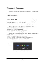
Front Panel LED
Power LED: ON: power on
OFF: power fail
LAN LED:
ON: connect
OFF: disconnect
Blinking: data transmit
When the CPE powers on, the LED indicates the CPE states as follow.
Only Red LED is Blinking: synchronization
Only Yellow LED is Blinking: authentication
Only Green LED is Blinking: DHCP client negotiation
After the CPE has connected to the base station, the signal strength LED are
defined as follow.
Only Red LED is ON: the signal is weak. (CINR<8dB)
Yellow LED is ON: the signal strength is medium. (8dB
≤
CINR<15dB)
Green LED is ON: the signal strength is good. (15dB
≤
CINR)
Figure 1-1 Indoor CPE Front Panel LED
Содержание ASMAX2300
Страница 4: ...iii Figure 2 34 Reboot Confirmation 2 32 ...
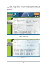
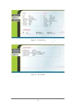
Страница 9: ...2 5 Figure 2 4 Network Status Figure 2 5 Device Status ...
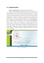
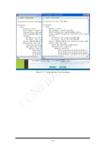
Страница 16: ...2 12 Figure 2 12 Authentication View Certificates ...
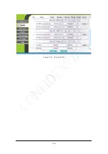
Страница 20: ...2 16 Figure 2 16 Firewall Filter ...
Страница 22: ...2 18 Figure 2 18 DHCP Server Disabled ...
Страница 27: ...2 23 Figure 2 23 DDNS Disabled ...
Страница 29: ...2 25 Figure 2 24 TR 069 Figure 2 25 TR 069 Certificate File Upload ...
Страница 33: ...2 29 Figure 2 30 Web Upgrade Summary Figure 2 31 TFTP Upgrade ...

