AirPro 785247264322 Скачать руководство пользователя страница 4

1. 

To reduce the risk of electric shock, ensure electricity 

has been turned off at the circuit breaker or fuse box 

before beginning.

2. 

All wiring must be in accordance with the National 

Electrical Code ANSI/NFPA 70-1999 and local electrical codes. 

Electrical installation should be performed by a 

qualified licensed electrician.

3. 

CAUTION: To reduce the risk of personal injury, use only 

the screws provided with the electrical box. 

4. 

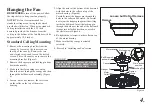
The outlet box and support structure must be securely 

mounted and capable of reliably supporting 35 lbs. (15.9 

kg). Use only UL Listed outlet boxes marked “Acceptable 

for Fan Support of 35 lbs. (15.9 kg) or less.”

5. 

The fan must be mounted with a minimum of 7 feet  

clearance from the trailing edge of the blades to the floor.

6. 

Do not operate reversing switch while fan blades are in 

motion. Fan must be turned off and blades stopped before 

reversing blade direction.

7. 

Avoid placing objects in path of the blades.

8. 

To avoid personal injury or damage to the fan and other 

items, be cautious when working around or 

cleaning the fan.

9. 

Do not use water or detergents when cleaning the fan or fan 

blades. A dry dust cloth or lightly dampened cloth will be 

suitable for most cleaning. 

10. 

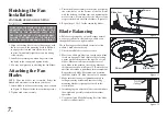
After making electrical connections, spliced conductors 

should be turned upward and pushed carefully up into 

electrical box. The wires should be spread apart with the 

grounded conductor and the equipment-grounding 

conductor on one side of the electrical box and ungrounded 

conductor on the other side of the electrical box.

11. 

Electrical diagrams are for reference only. Light kits that 

are not packed with the fan must be UL Listed and marked 

suitable for use with the model fan you are installing. 

Switches must be UL General Use Switches. Refer to the 

instructions packaged with the light kits and switches for 

proper assembly.

12. 

All set screws must be checked and retightened where 

necessary before installation.

1. Safety Rules

READ AND SAVE THESE INSTRUCTIONS

TO REDUCE THE RISK OF FIRE, ELECTRIC SHOCK OR PERSONAL 

INJURY, MOUNT TO OUTLET BOX MARKED “ACCEPTABLE FOR FAN 

SUPPORT OF 35LBS. (15.9 KG) OR LESS”, AND USE SCREWS PRO-

VIDED WITH THE OUTLET BOX.

TO REDUCE THE RISK OF PERSONAL INJURY, DO NOT BEND THE 

BLADE BRACKETS (ALSO REFERRED TO AS (“FLANGES”) DURING 

ASSEMBLY OR AFTER INSTALLATION. DO NOT INSERT OBJECTS IN 

THE PATH OF THE BLADES.

TO REDUCE THE RISK OF SHOCK, THIS FAN MUST BE INSTALLED 

WITH AN ISOLATION WALL CONTROL/SWITCH.

Содержание 785247264322

Страница 1: ...P250081 93157633_A...

Страница 2: ...g and reinstallation of fans or parts for repair or replacement Progress Lighting will not assume liability or responsibility for damages including incidental or consequential caused by improper insta...

Страница 3: ...1 2 3 9 10 11 12 Safety Rules Unpacking Your Fan Installing Your Fan Operating Your Fan Care of Your Fan Troubleshooting Specifications Table of Contents...

Страница 4: ...lades A dry dust cloth or lightly dampened cloth will be suitable for most cleaning 10 After making electrical connections spliced conductors should be turned upward and pushed carefully up into elect...

Страница 5: ...2 d Extra blade bracket screw 5 Fan Motor Assembly 6 Light Kit 7 Blades 5 8 Shades 4 9 Bulbs 4 1 Mounting Bracket inside canopy 2 4 25 Ball Downrod Assembly hanger pin and locking pin pre attached 3 C...

Страница 6: ...l box Note You may need a longer downrod to maintain proper blade clearance when installing on a steep sloped ceiling The maximum angle allowable is 30 If the canopy touches downrod remove the decorat...

Страница 7: ...ball downrod assembly Figure 6 4 Loosen but do not remove the set screws on the collar on the top of the motor housing Figure 6 5 Align the holes at the bottom of the downrod with the holes in the co...

Страница 8: ...the electrical box Note that the flat side of the mounting bracket is toward the electrical box Figure 7 3 Tighten the two screws on the electrical box securely 4 Carefully lift the fan assembly up to...

Страница 9: ...low the steps below to connect the fan to your household wiring Use the wire connecting nuts supplied with your fan Secure the connectors with electrical tape Make sure there are no loose strands or c...

Страница 10: ...d The following procedure should correct most fan wobble Check after each step 1 Check that all blade screws are secure 2 Most fan wobble problems are caused when blade levels are unequal Check this l...

Страница 11: ...rews that were previously removed in step 1 6 Place the shatter resistant shade into the light kit assembly aligning the three flat areas on the top flange of the shatter resistant shade with the thre...

Страница 12: ...switch housing refer to figure 16 to opposite position and turn fan on again The fan blades will turn in the opposite direction and reverse airflow Figure 17 Figure 18 Warm weather Forward A downward...

Страница 13: ...anently lubricated sealed ball bearings MAKE SURE THE POWER IS OFF AT THE ELECTRICAL PANEL BOX BEFORE YOU ATTEMPT TO MAKE ANY REPAIRS REFER TO THE SECTION MAKING ELECTRICAL CONNECTIONS Fan will not st...

Страница 14: ...LIGHTS WATTS AIRFLOW CFM AIRFLOW EFFICIENCY HIGHER IS BETTER CFM WATT NET WEIGHT GROSS WEIGHT CUBE FEET 52 Low 120 10 62 1905 179 3 16 16 Lbs 18 74 Lbs 2 0 High 120 58 14 4587 78 9 2016 Progress Ligh...

Страница 15: ...Manual de instalaci n de ventilador de techo P250081 93157633_A...

Страница 16: ...alaci n del ventilador as como de las partes y piezas a reparar o reponer Progress Lighting no asumir responsabilidad alguna por da os incluso incidentales o consecuentes causados por instalaci n o ma...

Страница 17: ...1 2 3 9 10 11 12 Normas de seguridad C mo desempacar el ventilador C mo instalar el ventilador C mo usar el ventilador Cuidado del ventilador Soluci n de problemas Especificaciones Tabla de contenido...

Страница 18: ...r adecuado un pa o seco o ligeramente humedecido con que quitar el polvo 10 Despu s de concluir con las conexiones el ctricas debes voltear los conductores empalmados hacia arriba y empujarlos con cui...

Страница 19: ...soporte de aspas 4 Brazos de aspas 5 5 Conjunto del motor del ventilador 6 Kit de luces 7 Aspas 5 8 Pantallas 4 9 Bombillas 4 1 Soporte de montaje dentro de la cubierta 2 Conjunto de tubo bajante esf...

Страница 20: ...Nota Tal vez necesites un tubo bajante m s largo para mantener la altura m nima adecuada de las aspas al instalar el ventilador en un techo inclinado El ngulo m ximo permitido es 30 Si la cubierta toc...

Страница 21: ...ura 6 4 Afloja sin quitarlos los tornillos de fijaci n en el collar n de la parte superior de la carcasa de motor Figura 6 5 Alinea los orificios en la parte inferior del tubo bajante con aquellos del...

Страница 22: ...idos con ella Nota que el lado plano del soporte de montaje est hacia la caja el ctrica Figura 7 3 Aprieta bien los dos tornillos en la caja el ctrica 4 Con cuidado alza el conjunto del ventilador has...

Страница 23: ...r tu ventilador al circuito de tu hogar Usa las tuercas de conexi n de cables que vienen con tu ventilador Asegura los conectores con cinta aislante Aseg rate de que no haya conexiones ni cables suelt...

Страница 24: ...dimiento corregir en gran medida la oscilaci n del ventilador Verifica despu s de cada paso 1 Verifica que todos los tornillos de las aspas est n asegurados 2 La mayor a de los problemas de oscilaci n...

Страница 25: ...Coloca la pantalla resistente a impacto en el conjunto del kit de luces alineando las tres reas planas en el reborde superior de dicha pantalla con las tres muescas salientes del conjunto del kit Gira...

Страница 26: ...la caja del interruptor ver figura 16 hacia la posici n opuesta y vuelve a prender el ventilador Las aspas del ventilador girar n en sentido contrario e invertir n el flujo del aire Figura 17 Figura...

Страница 27: ...ICO ANTES DE INTENTAR HACER REPARACIONES CONSULTA LA SECCI N C MO HACER CONEXIONES EL CTRICAS El ventilador no enciende El ventilador hace ruido 1 Verifica los fusibles o disyuntores principales y sec...

Страница 28: ...SIN LUCES VATIOS FLUJO DE AIRE CFM EFICIENCIA DE FLUJO DE AIRE M S ALTO ES MEJOR CFM W PESO NETO PESO BRUTO PIES C BICOS 52 1 32 m Baja 120 16 16 Lb 18 74 Lb 2 0 Alta 120 2016 Progress Lighting Inc 70...

Отзывы: