background image

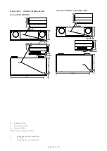
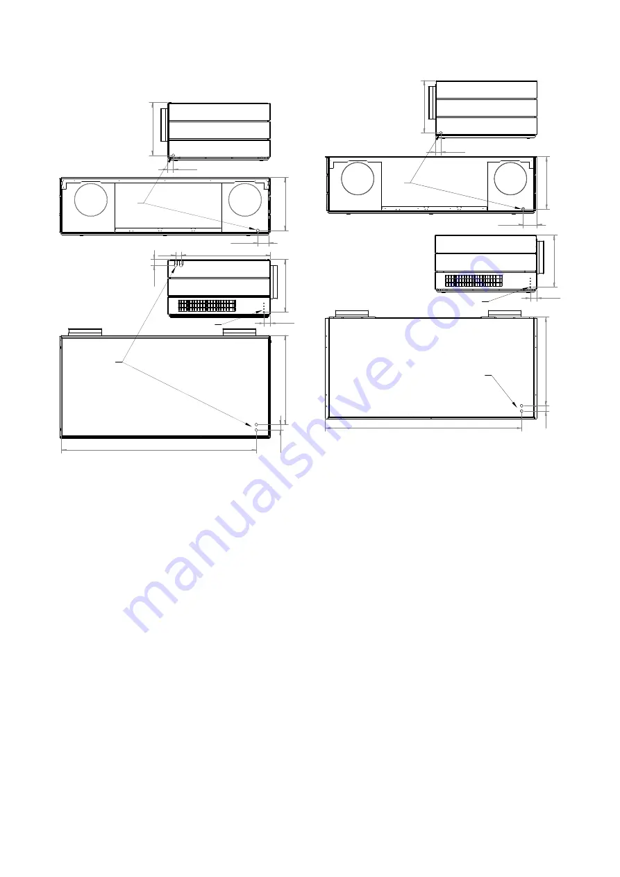
402*

49**

679**

41

1479***

41

46*

678**

404*

82***

44**

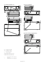
403*

8

7

6

44**

401-421*

400-420*

49**

106***

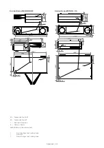
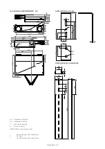
403-423*

679**

41

1504***

8

7

6

Appendix 2 - 30

Appendix 2 

Additional Dimensions

Connections AM 500

From top edge of wall / ceiling frame. 

** 

From wall. 

*** 

From left edge of wall / ceiling frame.

6  =  Condensate Drain
7  =  Electrical Connection
8  =  De Return
AM 500: Delivery is 

towards the front.

Connections AM 500 - CF (Ceiling Frame)

Содержание AM 150

Страница 1: ...1 2 2 3 3 AM 150 300 500 800 INSTALLATION...

Страница 2: ...rotected rooms The unit should not be used without the filters specified in the Operator s Manual The manufacturer cannot be held liable for dam agearisingfromuseorinstallingincontravention of these i...

Страница 3: ...he wall frame or cooling module 11 3 5 1 Installation with Ceiling Frame 12 3 6 Installation of the Air Handling Unit AM 150 AM 150 with CC 150 Cooling Module and AM 300 13 3 6 1 Assembling the AM 150...

Страница 4: ...HDIDE CC with Cooling Module 24 Isometric View 25 Model Versions AM 500 and 800 29 Appendix 2 Additional Dimensions 30 Connections AM 500 30 Connections AM 500 CC 31 Connections AM 800 31 Connections...

Страница 5: ...aster air handling unit AM 2 Wall frame fitted for 1 or 3 3 Cooling module CC optional Cooling modules must be stored and transported on the case cover The unit may however be tipped up to 80 degrees...

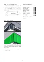
Страница 6: ...rrier are restored and fully functional once the unit has been installed Read this section Installation fully before starting installation 3 1 Positioning of the Air Handling Unit The diagram below sh...

Страница 7: ...iciently sound or when the unit is to be fitted in a free suspended position Not at the AM 150 and AM 300 The holes for securing the ceiling brackets are at the top of the unit and the cooling module...

Страница 8: ...eaks and an increased noise level during operation of the unit It is recommended that the duct holes be drilled 10 15 mm larger than indicated on the drawings as this will allow for subsequent insulat...

Страница 9: ...ducts and the frame 1 2 or 1 2 in accordance with Dimensional Drawings 5 Fit the frame in a horizontal position 1 2 or 1 2 3 Mark the holes for the ducts according to Appendix 1 Dimensional Drawings 4...

Страница 10: ...Appropriate lifting equipment is used to lift the cooling module into place on the wall frame We would point out that when lifting the cooling module a protective underlay must be placed beneath the...

Страница 11: ...the unit a protective underlay must be placed beneath the service cover to prevent scratches to the service cover This underlay may for example be strong clean cardboard or equivalent 3 Push the Airma...

Страница 12: ...mm 2 Lift the air handling unit up to the ceiling using appropriate lifting equipment We would point out that when lifting the unit a protective underlay must be placed beneath the service cover to p...

Страница 13: ...ule by screwing it onto the frame 5 Repeat on the other side 6 Adjust the air handling unit into a horizontal position with the adjusting screws For AM 150 with CC 150 it may be necessary to adjust be...

Страница 14: ...nnected on the hinge side from the cabinet to the service cover 5 Carefullyclosetheservicecoverwhileitissupported The service cover is heavy First close the locks on the inlet side and then the locks...

Страница 15: ...level it is important that the ducts should not get twisted or compressed against the exhaust air spigot and supply air spigot of the unit Remember to seal around the penetrations See section Sealing...

Страница 16: ...cessary 3 11 Fitting of Panels The panels must only be fitted once the unit complete with all equipment has been fitted and connected and the functions of the unit thoroughly tested Not at the AM 150...

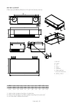
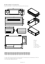
Страница 17: ...Appendix 1 17 Appendix 1 Dimensional Drawings AM 150 AM 150 CC with Cooling Module and AM 300 See the attached dimensional drawing...

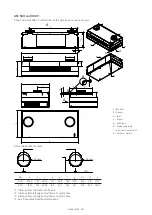
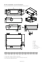
Страница 18: ...18 AM 500 and 800 H Shown here AM 500 HB with Extract on the right side and one panel row 1 Distance from top edge of wall frame to centre hole 2 Distance from left edge of wall frame without mountin...

Страница 19: ...from the wall to centre hole 2 Distance from left edge of wall frame to centre hole 3 Distance from top edge of wall frame to centre hole 4 See Appendix 2 Additional Dimensions AM 500 and 800 V Shown...

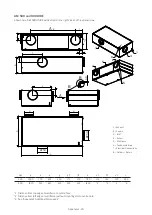
Страница 20: ...20 1 Distance from top edge of wall frame to centre hole 2 Distance from left edge of wall frame without mounting pin to centre hole 4 See Appendix 2 Additional Dimensions AM 500 800 AM 500 and 800 DI...

Страница 21: ...eiling Frame Shown here AM 500 HT CF with Extract on the right side and three panel rows 1 Distance from the wall to centre hole The vertical position of the handling unit can be adjusted up to 20 0 m...

Страница 22: ...to centre hole The vertical position of the handling unit can be adjusted up to 20 0 mm 2 Distance from left edge of ceiling frame to centre hole 4 See Appendix 2 Additional Dimensions AM 500 and 800...

Страница 23: ...endix 1 23 1 Distance from top edge of wall frame to centre hole 2 Distance from left edge of wall frame without mounting pin to centre hole 4 See Appendix 2 Additional Dimensions AM 500 and 800 H CC...

Страница 24: ...24 1 Distance from top edge of wall frame to centre hole 2 Distance from left edge of wall frame without mounting pin to centre hole 4 See Appendix 2 Additional Dimensions AM 500 and 800 HDIDE CC with...

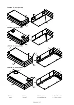
Страница 25: ...5 2 4 3 8 3 4 2 1 6 7 8 5 6 1 2 4 7 3 8 5 Appendix 1 25 1 Exhaust 2 Supply 3 Inlet 4 Extract 5 Wall Frame 6 Condensate Drain 7 Electr Connection 8 Delivery Return Isometric View AM 500H AM 800H AM 50...

Страница 26: ...5 3 1 6 7 2 4 8 5 3 4 2 1 6 7 8 5 1 2 7 4 3 8 6 5 Appendix 1 26 1 Exhaust 2 Supply 3 Inlet 4 Extract 5 Wall Frame 6 Condensate Drain 7 Electr Connection 8 Delivery Return AM 500V AM 800V AM 500V DIDE...

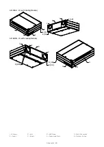
Страница 27: ...3 5 8 4 6 6 7 1 2 3 5 Appendix 1 27 1 Exhaust 2 Supply 3 Inlet 4 Extract 5 Ceiling Frame 6 Condensate Drain 7 Electr Connection 8 Delivery Return AM 500 H CF Ceiling Frame AM 800H CF Ceiling Frame AM...

Страница 28: ...CC 6 CC 2 1 3 4 6 CC 8 5 7 6 CC 6 AM Appendix 1 28 1 Exhaust 2 Supply 3 Inlet 4 Extract 5 Wall Frame 6 Condensate Drain 7 Electr Connection 8 Delivery Return AM 500 H CC with Cooling Module AM 800H CC...

Страница 29: ...ons AM 500 and 800 Version T Inlet top Version C Inlet middle Version B Inlet bottom Version DI Ducted inlet Version DE Ducted Extract Version RE Supply and Exhaust with square spigots AM a b c d e 50...

Страница 30: ...04 8 7 6 Appendix 2 30 Appendix 2 Additional Dimensions Connections AM 500 From top edge of wall ceiling frame From wall From left edge of wall ceiling frame 6 Condensate Drain 7 Electrical Connection...

Страница 31: ...35 1830 55 47 792 8 7 7 6 1 Appendix 2 31 From top edge of wall ceiling frame From wall From left edge of wall ceiling frame 6 1 Condensate Drain AM 6 2 Condensate Drain CC 7 Electrical Connection 8 D...

Страница 32: ...55 440 409 55 47 1198 448 1830 439 8 6 2 7 6 1 6 2 7 Appendix 2 32 From top edge of wall ceiling frame From wall From left edge of wall ceiling frame 6 1 Condensate Drain AM 6 2 Condensate Drain CC 7...

Страница 33: ...50 144 699 152 55 439 70 448 1830 8 6 2 7 6 1 6 2 7 Appendix 2 33 From top edge of wall ceiling frame From wall From left edge of wall ceiling frame 6 1 Condensate Drain AM 6 2 Condensate Drain CC 7 E...

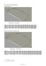
Страница 34: ...3 5 18 5 11 26 45 290 712 1162 1162 15 5 47 5 1835 5 1867 5 800 DE 3 5 18 5 11 26 45 290 712 1162 957 15 5 47 5 1835 5 1867 5 Appendix 2 34 Postioning of the Ceilling Brackets AM 500 and 800 AM Distan...

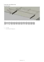
Страница 35: ...f g h i j k 500 145 232 595 682 772 9 121 811 1501 1612 800 42 263 350 713 800 910 9 121 966 1811 1922 Appendix 2 35 AM Postioning of the Ceilling Frame AM 500 and 800 From wall From left edge of ceil...

Страница 36: ...04 REV01 Version 6 2 2020 12 01 Errors omissions and changes excepted Original User Instructions Airmaster A S Industrivej 59 DK 9600 Aars Tel 45 98 62 48 22 info airmaster as com www airmaster as com...

Отзывы: