airmaster 2244030 Скачать руководство пользователя страница 7

7

ELECTRICAL CONNECTIONS

Before switching the product on, make sure that the voltage of your electricity supply is 
the same as that indicated on the rating plate. This product is designed to operate on 
230VAC 50Hz. Connecting it to any other power source may cause damage.

This product may be fitted with a non-rewireable plug. If it is necessary to change the 
fuse in the plug, the fuse cover must be refitted. If the fuse cover becomes lost or 
damaged, the plug must not be used until a suitable replacement is obtained.

If the plug has to be changed because it is not suitable for your socket, or due to 
damage, it should be cut off and a replacement fitted, following the wiring instructions 
shown below. The old plug must be disposed of safely, as insertion into a mains socket 
could cause an electrical hazard.

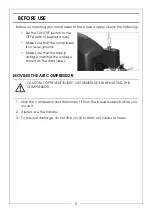
If the colours of the wires in the power cable of this product do not correspond with the 
markings on the terminals of your plug, proceed as follows.

• The 

Blue

 wire must be connected to the terminal marked 

N

 or coloured 

Black.

• The 

Brown

 wire must be connected to the terminal marked 

L

 or coloured 

Red.

• The 

Yellow and Green

 wire must be c.onnected to the terminal marked 

or 

 or coloured 

Green

.

We strongly recommend that this machine is connected to the mains supply 
via a Residual Current Device (RCD). If in any doubt, consult a qualified 
electrician. DO NOT attempt any repairs yourself.

WARNING! READ THESE ELECTRICAL SAFETY INSTRUCTIONS 
THOROUGHLY BEFORE CONNECTING THE PRODUCT TO THE 
MAINS SUPPLY.

WARNING! THE WIRES IN THE POWER CABLE OF THIS PRODUCT 
ARE COLOURED IN ACCORDANCE WITH THE FOLLOWING CODE:
BLUE = NEUTRAL      BROWN = LIVE     YELLOW AND GREEN = 
EARTH

Plug must be BS1363/A approved.

Always fit a 13 Amp fuse.

Ensure that the outer sheath of the cable is firmly held by the clamp

Neutral

(Blue)

Live

(Brown)

Earth

(Green and Yellow)

Содержание 2244030

Страница 1: ...OPERATION MAINTENANCE INSTRUCTIONS ORIGINAL INSTRUCTIONS GC1020 REV 6 24L OIL FREE AIR COMPRESSOR MODEL NO TIGER 7 250 PART NO 2244030 ...

Страница 2: ...RANTEE This product is guaranteed against faulty manufacture for a period of 12 months from the date of purchase Please keep your receipt as proof of purchase This guarantee is invalid if the product is found to have been abused or tampered with in any way or not used for the purpose for which it was intended Faulty goods should be returned to their place of purchase no product can be returned to ...

Страница 3: ...self against electric shock Never operate the compressor in wet or damp locations 4 NEVER over reach Keep your proper footing and balance at all times to enable better control of the compressor in unexpected situations 5 NEVER attempt any complex repairs yourself If you have a technical problem contact your local dealer 6 ALWAYS store the compressor out of reach of children 7 ALWAYS protect your h...

Страница 4: ...pressure of 10 bar or more should be used Never attempt to repair damaged hoses 8 NEVER abuse the compressor by standing on it AIRLINE HOSES 1 ALWAYS ensure that equipment or power tools used in conjunction with the compressor have a safe working pressure exceeding that of the machine 2 ALWAYS keep the air hose away from any attached power tools and ensure that the operator is not restricted by th...

Страница 5: ...the compressor repaired by a qualified service engineer Do not use the compressor if the On Off switch does not operate correctly 7 KEEP THE MOTOR AIR VENTS CLEAR Keep the motor vents clear and free from dust Wipe regularly to maintain an adequate supply of clean air Avoid using in dusty conditions 8 OPERATE THE COMPRESSOR AT THE CORRECT VOLTAGE Make sure that the mains supply voltage is the same ...

Страница 6: ...ressor could start automatically in the event of a power cut and subsequent reset Do not carry the compressor while it is connected to the power source or when the receiver is filled with compressed air Risk of electric shock The compressor must be disconnected from the mains supply before removing any covers Do not use in a damp environment This compressor should always be started or stopped by m...

Страница 7: ...e colours of the wires in the power cable of this product do not correspond with the markings on the terminals of your plug proceed as follows The Blue wire must be connected to the terminal marked N or coloured Black The Brown wire must be connected to the terminal marked L or coloured Red The Yellow and Green wire must be c onnected to the terminal marked E or or coloured Green We strongly recom...

Страница 8: ...mpressor Use the washers and spring washer in the positions shown ATTACH THE SUPPORT FEET Insert the support feet into the position shown FIT THE AIR FILTER 1 If one is fitted remove the travel plug 2 Screw the air filter into position The air filter must be hand tight only ...

Страница 9: ...sor is on level ground Make sure that the supply voltage matches the voltage shown on the data label MOVING THE AIR COMPRESSOR 1 Stop the compressor and disconnect it from the power supply before you move it 2 Always use the handle 3 To prevent damage do not lift by or put strain on valves or hoses CAUTION TO PREVENT INJURY GET ASSISTANCE WHEN LIFTING THIS COMPRESSOR ...

Страница 10: ...osition NOTE The outlet valve is shown without the air hose fitted for clarity TURNING THE COMPRESSOR ON 1 Plug the compressor into the power supply 2 Lift the On Off button The compressor will operate until the reservoir is fully pressurised It will then shut down The compressor will start up again when the pressure in the reservoir decreases WARNING BEFORE CONNECTING AIR TOOLS MAKE SURE THAT YOU...

Страница 11: ...OUTPUT PRESSURE When viewed from the front the left hand outlet valve is adjustable The right hand outlet valve will only supply the full reservoir pressure and is not adjustable 1 Use the pressure regulator to set the output pressure of the left hand outlet valve Turn clockwise to increase the pressure Turn counterclockwise to decrease the pressure GAUGES 1 The reservoir pressure gauge shows the ...

Страница 12: ...he hose TURNING THE COMPRESSOR OFF 1 Follow steps 1 3 in Removing Tools From The Air Hose above 2 Disconnect the compressor from the power supply 3 Slowly open one of the outlet valve to depressurise the reservoir You will hear a hissing sound as the reservoir depressurises Do not leave the compressor unattended if the reservoir is pressurised WARNING ALWAYS SET THE PRESSURE REGULATOR TO ZERO BEFO...

Страница 13: ... thermal overload device If the motor gets too hot the thermal overload device cuts the power which prevents damage to the motor If the thermal overload device operates let the motor cool down for 5 minutes and push the reset button If you start the compressor and the overload cutout operates again stop the compressor and disconnect from the power supply and have your compressor examined by a qual...

Страница 14: ...s 1 Remove the filter from the compressor 2 Remove the filter cover from the filter 3 Remove the filter from the filter cover 4 Clean the sponge and the filter cover using a soft brush If necessary the filter can be carefully cleaned in warm soapy water Rinse and let the filter dry completely before refitting 5 Make sure that the filter and filter cover are replaced into position If the filter is ...

Страница 15: ...hese may be aggressive to the plastic parts Always disconnect the hose and any air tools from the compressor before cleaning STORAGE Disconnect the mains plug and ventilate the compressor and any connected pneumatic tools Store the compressor in a dry location Always store upright ENVIRONMENTAL RECYCLING POLICY By purchasing this product the customer is taking on the obligation to comply with curr...

Страница 16: ...et pressure and overheats easily Compressor head gasket blown or valve broken 1 Return the machine to your nearest service agent Compressor does not start The reservoir has already fully pressurised 1 Open drain valve to expel air Compressor should start again when pressure reduces Air leaking from the non return valve when the compressor is not running Faulty non return valve 1 Drain receiver com...

Страница 17: ...17 DECLARATION OF CONFORMITY ...

Страница 18: ...18 COMPONENT PARTS No Description No Description 1 Bolt M6 25 38 Spring Washer 2 Bolt M6 35 39 Nut M3 3 Spring Washer 40 Capacitor ...

Страница 19: ...lt M4 20 54 Plug 18 Spring Washer 4 55 O Ring 19 Bearing 6005 2RS 56 24L Tank 20 Pin 4 x14 57 Nut M8 21 Crank 58 Spring Washer 8 22 Screw M8 35 left 59 Wheel 23 Crankcase 60 Axle 24 Bearing 6204 RS 61 Check Valve 25 Rotor 62 Drain Valve 1 4 Inch 26 Stator assembly 63 M8 x 30 bolt 27 Bearing 6202 64 Absorber 28 Corrugated Washer 65 Power Cable 29 Motor Bracket 66 Quick Coupler 30 Circlip 14 67 Regu...

Страница 20: ......

Отзывы: