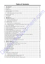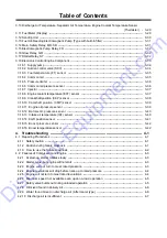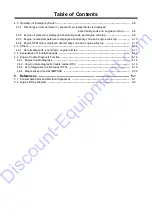
Table of Contents
1. Specification
--------------------------------------------------------------------------------------
1-1
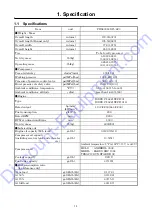
1.1 Specifications -----------------------------------------------------------------------------------------------------------
1-1
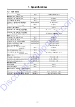
1.2 Set Value -----------------------------------------------------------------------------------------------------------------
1-2
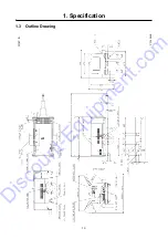
1.3 Outline Drawing --------------------------------------------------------------------------------------------------------
1-3
1.4 Internal Components and Part Names ----------------------------------------------------------------------------
1-5
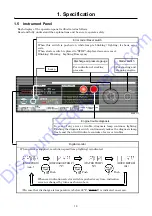
1.5 Instrument Panel -------------------------------------------------------------------------------------------------------
1-8
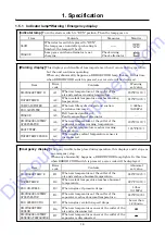
1.5.1
Indicator lamp
・
Warning / Emergency display ---------------------------------------------------------------
1-9
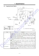
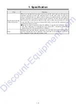
1.6 Capacity Control Device ----------------------------------------------------------------------------------------------
1-10
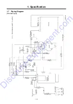
1.7 Piping Diagram ---------------------------------------------------------------------------------------------------------
1-12
1.8 Fuel Piping ---------------------------------------------------------------------------------------------------------------
1-14
2. Maintenance ---------------------------------------------------------------------------------------
2-1
2.1 Cautions for Overhauling ---------------------------------------------------------------------------------------------
2-1
2.1.1
Precautions before starting work -------------------------------------------------------------------------------
2-1
2.1.2
Disassembly and reassembly -----------------------------------------------------------------------------------
2-1
2.2 Tightening Torque -----------------------------------------------------------------------------------------------------
2-3
2.2.1
General bolts and nuts tightening torque ---------------------------------------------------------------------
2-3
2.2.2
Tightening torque of such important quality parts as bolts and nuts -----------------------------------
2-4
2.3 How to Adjust Regulator ---------------------------------------------------------------------------------------------
2-7
2.4 Maintenance and Adjustment of Pressure Control Valve ----------------------------------------------------
2-8
2.5 Change O-ring of Unloader ------------------------------------------------------------------------------------------
2-10
2.6 Change O-ring of Auto-relief Valve and Vacuum Relief Valve ----------------------------------------------
2-10
2.7 Change Oil Separator -------------------------------------------------------------------------------------------------
2-11
2.8 Change of Pellet assembly of By-pass Valve -------------------------------------------------------------------
2-12
2.9 Clean the Strainer Provided inside the Engine Feed Pump -------------------------------------------------
2-13
2.10 Supply Grease to Trailer Hub Bearing ----------------------------------------------------------------------------
2-13
2.11 Supply Grease to Leaf Spring Pin ---------------------------------------------------------------------------------
2-13
2.12 Check and Confirm that the Fixing Bolts for the Drawbar are Properly Tightened ---------------------
2-13
2.13 Manual Air Bleeding Method for Fuel Line System ------------------------------------------------------------
2-14
2.14 Clean inside of Fuel Tank --------------------------------------------------------------------------------------------
2-14
2.15 Clean Drain Separator (Aftercooler type only) ------------------------------------------------------------------
2-15
2.16 Values of Various Adjustments of Engine ------------------------------------------------------------------------
2-15
2.17 Suction Control Valve (SCV) Replacement Procedure -------------------------------------------------------
2-16
3. Electric
System -----------------------------------------------------------------------------------
3-1
3.1 Electronic Control System of Engine ------------------------------------------------------------------------------
3-1
3.1.1
Electronic control fuel injection system (Common rail type) ---------------------------------------------
3-1
3.1.2
EGR (Exhaust gas recirculation) control ---------------------------------------------------------------------
3-3
3.1.3
Acceleration control ----------------------------------------------------------------------------------------------
3-4
3.1.4
Preheating control -------------------------------------------------------------------------------------------------
3-4
3.2 Accelerator Controller -------------------------------------------------------------------------------------------------
3-5
3.3 Engine Controller (ECM) ---------------------------------------------------------------------------------------------
3-8
3.4 Emergency Controller -------------------------------------------------------------------------------------------------
3-17
3.5 Alternator -----------------------------------------------------------------------------------------------------------------
3-25
3.6 Starter ---------------------------------------------------------------------------------------------------------------------
3-26
3.7 Solenoid Valve for Starting Unloader -----------------------------------------------------------------------------
3-27
3.7.1
Unloader piston actuation:SV1 -------------------------------------------------------------------------------
3-27
3.7.2
Unloader spring chamber negative pressure:SV2 ------------------------------------------------------
3-27
3.8 Air Filter Indicator (Engine / Air-end common) -------------------------------------------------------------------
3-28
3.9 Pressure Sensor (Secondary pressure of regulator detect) -------------------------------------------------
3-28
Discount-Equipment.com
Содержание PDS400S-6C3
Страница 1: ...www discount equipment com D i s c o u n t E q u i p m e n t c o m ...
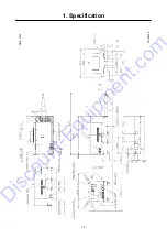
Страница 9: ...1 Specification 1 3 1 3 Outline Drawing PC14064E Unit in D i s c o u n t E q u i p m e n t c o m ...
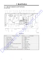
Страница 10: ...1 Specification 1 4 PC14064E Unit mm D i s c o u n t E q u i p m e n t c o m ...
Страница 18: ...1 Specification 1 12 1 7 Piping Diagram Standard type A120194E D i s c o u n t E q u i p m e n t c o m ...
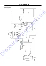
Страница 19: ...1 Specification 1 13 Aftercooler type A120195E D i s c o u n t E q u i p m e n t c o m ...
Страница 20: ...1 Specification 1 14 1 8 Fuel Piping PC13053E D i s c o u n t E q u i p m e n t c o m ...
Страница 56: ...3 Electric System 3 18 1 Exterior connection drawing PC12069E D i s c o u n t E q u i p m e n t c o m ...
Страница 101: ...5 3 5 2 Engine Wiring Diagram PC13087E PC13088 D i s c o u n t E q u i p m e n t c o m ...


