background image

Page 14

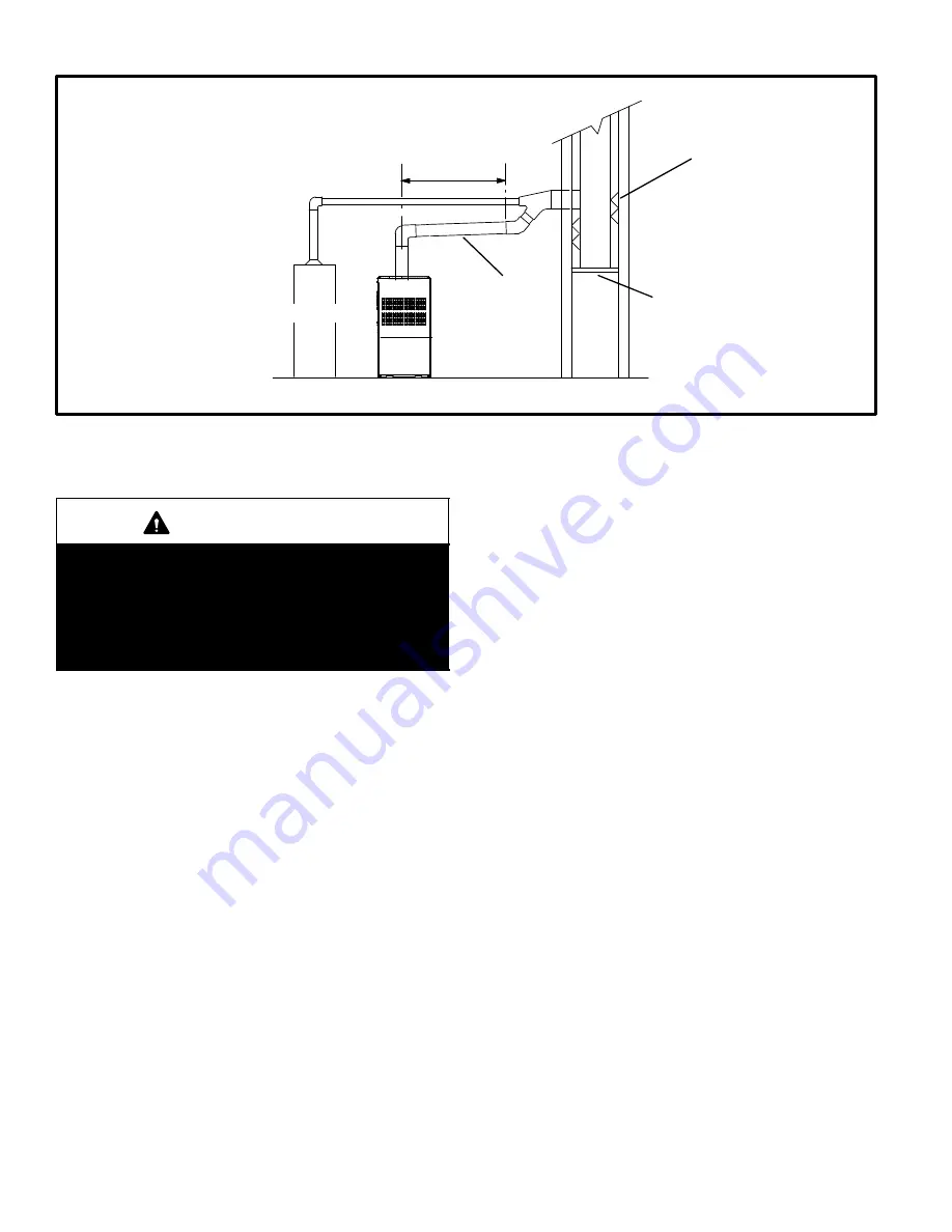
FIGURE 17

Common Venting Using Tile−Lined Interior Masonry Chimney and Combined Vent Connector

MINIMUM LENGTH = AS SHORT AS PRACTICAL. 
FOR MAXIMUM LENGTH SEE NOTE TO LEFT

INTERIOR TILE−LINED
MASONRY CHIMNEY

NOTE − the chimney must be properly
sized per provided venting tables or
lined with listed metal lining system.

PERMANENTLY
SEALED FIREPLACE
OPENING

VENT

CONNECTOR

NOTE− Refer to provided venting
tables for installations.

FURNACE

OTHER

APPLIANCE

DO NOT insulate the space between the liner and the
chimney wall with puffed mica or any other loose gran-
ular insulating material.

IMPORTANT

SINGLE appliance venting of a fan-assisted furnace
into a tile-lined masonry chimney (interior or outside
wall) is PROHIBITED. The chimney must first be lined
with either type B1 vent or an insulated single wall
flexible vent lining system which has been sized ac-
cording to the provided venting tables and the vent
pipe manufacturer’s instructions.

A fan−assisted furnace may be commonly vented into an
existing lined masonry chimney if the following conditions
are met:

S

  The chimney is currently serving at least one drafthood−

equipped appliance;

S

  The vent connectors and chimney are sized according

to the provided venting tables.

If type B1 double-wall vent is used inside a chimney, no oth-
er appliance can be vented into the chimney. The outer wall
of type B1 vent pipe must not be exposed to flue products.

A type B1 vent or masonry chimney liner shall terminate
above the roof surface with a listed cap or a listed roof as-
sembly according to the terms of their respective listings
and the vent manufacturer’s instructions.

When inspection reveals that an existing chimney is not
safe for the intended purpose, it shall be rebuilt to conform
to nationally recognized standards, lined or relined with
suitable materials, or replaced with a gas vent or chimney
suitable for venting 80AF1DF series units. The chimney
passageway must be checked periodically to ensure that it
is clear and free of obstructions.

Do not install a manual damper, barometric draft regulator,
or flue restrictor between the furnace and the chimney.

Never connect a Category I appliance to a chimney that is
servicing a solid−fuel appliance. If a fireplace chimney flue
is used to vent this appliance, the fireplace opening must
be permanently sealed.

A type B or listed chimney lining system that passes
through an unused masonry chimney flue is not considered
to be exposed to the outdoors.

General Venting Requirements

Vent all 80AF1DF furnaces according to these instructions:

 1 − Vent diameter recommendations and maximum allow-

able piping runs are found in the provided venting
tables.

 2 − In no case should the vent or vent connector diameter

be less than the diameter specified in the provided
venting tables.

 3 − The minimum vent capacity determined by the sizing

tables must be less than the low fire input rating and the
maximum vent capacity must be greater than the high
fire input rating.

 4 −

Single appliance vents −

 If the vertical vent or tile-lined

chimney has a larger diameter or flow area than the
vent connector, use the 

vertical vent diameter

 to de-

termine the 

minimum vent capacity

 and the 

vent

connector diameter

 to determine the 

maximum vent

capacity

. The flow area of the vertical vent, however,

shall not exceed 7 times the flow area of the listed ap-
pliance categorized vent area, drafthood outlet area or
flue collar area unless designed according to approved
engineering methods.

 5 −

Multiple appliance vents −

 The flow area of the largest

section of vertical vent or chimney shall not exceed 7
times the smallest listed appliance categorized vent
area, drafthood outlet area or flue collar area unless de-
signed according to approved engineering methods.

Содержание 80AF1DF

Страница 1: ...lteration service or maintenance can cause property damage person al injury or loss of life Installation and service must be performed by a licensed professional installer or equivalent service agency or the gas supplier TABLE OF CONTENTS Unit Dimensions 2 Parts Arrangement 3 80AF1DF Gas Furnace 4 Shipping and Packing List 4 Safety Information 4 Use of Furnace as a Construction Heater 5 General 5 ...

Страница 2: ...4 705 19 1 4 489 6 5 8 168 Right 7 1 8 181 Left 5 3 8 137 Right 2 1 8 54 Left 33 838 19 7 16 494 9 16 14 B Supply Air Supply Air 9 16 14 9 16 14 3 1 8 79 9 16 14 9 16 14 19 7 16 494 3 4 19 3 4 19 80AF1DF Model No A B C D in mm in mm in mm in mm 045P12A 070P12A 14 1 2 368 13 3 8 340 13 330 4 3 4 121 090P16B 17 1 2 446 16 3 8 416 16 406 6 1 4 159 110P20C 21 533 19 7 8 504 19 1 2 495 8 203 ...

Страница 3: ...Page 3 Parts Arrangement FIGURE 1 Blower Assembly Integrated Control Flue Chase Access Panel Gas Valve Burner Assemlby Combustion Air Inducer Heat Exchanger ...

Страница 4: ...e must be made around the air open ings into the vestibule area In order to ensure proper unit operation combustion and ventilation air supply must be provided according to the current National Fuel Gas Code Vent installations must be consistent with the venting tables in this instruction and applicable provisions of local building codes This furnace is CSA International certified for installation...

Страница 5: ...ined D Air filters must be installed in the system and must be maintained during construction D Air filters must be replaced upon construction comple tion D The input rate and temperature rise must be set per the furnace rating plate D One hundred percent 100 outdoor air must be pro vided for combustion air requirements during construc tion Temporary ducting may supply outdoor air to the furnace D...

Страница 6: ...entila tion air requirements as well as all local codes CAUTION Insufficient combustion air can cause headaches nausea dizziness or asphyxiation It will also cause excess water in the heat exchanger resulting in rust ing and premature heat exchanger failure Excessive exposure to contaminated combustion air will result in safety and performance related problems Avoid exposure to the following subst...

Страница 7: ... permanent openings between the two spaces Each opening must have a minimum free area of 1 square inch 645 mm2 per 1 000 Btu 29 kW per hour of total input rating of all gas fired equipment in the confined space Each opening must be at least 100 square inches 64516 mm2 One opening shall be within 12 inches 305 mm of the top of the enclosure and one opening within 12 inches 305 mm of the bottom See ...

Страница 8: ...ne square inch 645 mm2 per 4 000 Btu 1 17 kW per hour of the total input rating of all equip ment in the enclosure CHIMNEY OR GAS VENT WATER HEATER OUTLET AIR VENTILATION LOUVERS Each end of attic INLET AIR Ends 12 in above bottom FURNACE FIGURE 5 EQUIPMENT IN CONFINED SPACE ALL AIR FROM OUTSIDE OUTLET AIR INLET AIR WATER HEATER CHIMNEY OR GAS VENT NOTE Each air duct opening shall have a free area...

Страница 9: ...e clearances 24 inches 610 mm at unit front The unit must be level NOTE Units with 1 2 hp blower motors are equipped with three flexible legs and one rigid leg See figure 7 The rigid leg is equipped with a shipping bolt and a flat white plastic washer rather than the rubber mounting grommet used with a flexible mounting leg The bolt and washer must be removed before the furnace is placed into oper...

Страница 10: ...tible wood floor if an optional additive base is installed between the furnace and the combustible floor FIGURE 9 WARNING Improper installation of the furnace can result in per sonal injury or death Combustion and flue products must never be allowed to enter the return air system or the living space Use screws and joint tape to seal the return air system to the furnace In platform installations wi...

Страница 11: ...eparately See table 2 for opening size to cut in floor CAUTION The furnace and downflow combustible flooring base shall not be installed directly on carpeting tile or other combustible material other than wood floor ing 80AF1DF UNIT SUPPLY AIR PLENUM DOWNFLOW COMBUSTIBLE FLOORING BASE PROPERLY SIZED FLOOR OPENING FIGURE 11 TABLE 2 COMBUSTIBLE FLOOR OPENING SIZE Cabinet Width Front to Rear Side to ...

Страница 12: ...inches A 14 1 2 14 x 25 x 1 1 B 17 1 2 16 x 25 x 1 1 C 21 20 x 25 x 1 1 Duct Sytem Use industry approved standards such as those pub lished by Air Conditioning Contractors of America or Ameri can Society of Heating Refrigerating and Air Conditioning Engineers to size and install the supply and return air duct system This will result in a quiet and low static system that has uniform air distributio...

Страница 13: ...mechanical fas tener to firmly secure the vent pipe to the round collar of the flue transition If self drilling screws are used to attach the vent pipe it is recommended that three be used Drive one self drilling screw through the front and one through each side of the vent pipe and collar See figure 15 Install the first vent connector elbow at a minimum of six inches 152 mm from the furnace vent ...

Страница 14: ...ed standards lined or relined with suitable materials or replaced with a gas vent or chimney suitable for venting 80AF1DF series units The chimney passageway must be checked periodically to ensure that it is clear and free of obstructions Do not install a manual damper barometric draft regulator or flue restrictor between the furnace and the chimney Never connect a Category I appliance to a chimne...

Страница 15: ...ch shall be assembled according to the manufacturer s instructions Joints between sections of single wall connector piping shall be fastened by screws or other approved means 13 When the vent connector used for Category I ap pliances must be located in or pass through a crawl space attic or other areas which may be cold that por tion of the vent connector shall be constructed of listed double wall...

Страница 16: ... 22 339 5 22 65 30 130 39 219 49 330 10 29 59 40 121 51 206 64 315 15 35 53 48 112 61 195 76 301 20 0 0 97 0 202 0 349 0 540 2 10 75 14 149 18 250 20 377 5 21 71 29 143 38 242 47 367 10 28 64 38 133 50 229 62 351 15 34 58 46 124 59 217 73 337 20 48 52 55 116 69 206 84 322 30 0 0 100 0 213 0 374 0 587 2 9 81 13 166 14 283 18 432 5 21 77 28 160 36 275 45 421 10 27 70 37 150 48 262 59 405 15 33 64 44...

Страница 17: ... 225 115 337 5 51 63 75 128 102 216 144 326 10 NA NA 95 116 128 201 182 308 15 NA NA NA NA 158 186 220 290 20 0 35 96 54 200 78 346 114 537 2 37 74 56 148 78 248 113 375 5 50 68 73 140 100 239 141 363 10 NA NA 93 129 125 223 177 344 15 NA NA NA NA 155 208 216 325 20 NA NA NA NA 186 192 254 306 30 0 34 99 53 211 76 372 110 584 2 37 80 55 164 76 281 109 429 5 49 74 72 157 98 271 136 417 10 NA NA 91 ...

Страница 18: ...5 1 21 50 33 89 47 142 64 220 2 22 53 35 96 49 153 66 235 3 24 55 36 102 51 163 68 248 20 1 21 54 33 99 46 157 62 246 2 22 57 34 105 48 167 64 259 3 23 60 35 110 50 176 66 271 30 1 20 62 31 113 45 181 60 288 2 21 64 33 118 47 190 62 299 3 22 66 34 123 48 198 64 309 TABLE 8 Common Vent Capacity Type B Double Wall Vents with Type B Double Wall Connectors Serving Two or More Category I Appliances Ven...

Страница 19: ... 278 2 51 62 81 115 117 185 177 290 3 54 64 85 119 122 193 185 300 NOTE Single appliance venting configurations with zero lateral lengths are assumed to have no elbows in the vent system For all other vent configurations the vent system is assumed to have two 90 elbows For each additional 90 elbow or equivalent for example two 45 elbows equal one 90 elbow beyond two the maximum capacity listed in ...

Страница 20: ...urn all doors widows exhaust fans fireplace damp ers and any other gas burning appliances to their pre vious mode of operation 7 If a venting problem is found during any of the preced ing tests the common venting system must be modi fied to correct the problem Resize the common venting system to the minimum vent pipe size determined by using the appropriate tables in Appendix G These are in the cu...

Страница 21: ... 04 2400 67 96 2250 63 71 2050 58 05 1950 55 22 1850 52 38 3 76 2 3 068 77 927 11000 311 48 7700 218 03 6250 176 98 5300 150 07 4750 134 50 4300 121 76 3900 110 43 3700 104 77 3450 97 69 3250 92 03 NOTE Capacity given in cubic feet m3 of gas per hour and based on 0 60 specific gravity gas GROUND JOINT UNION AUTOMATIC GAS VALVE with manual shut off valve FIELD PROVIDED AND INSTALLED GROUND JOINT UN...

Страница 22: ...re 23 for schematic wiring diagram and trou bleshooting The power supply wiring must meet Class I restrictions Protected by either a fuse or circuit breaker select circuit protection and wire size according to unit nameplate NOTE Unit nameplate states maximum current draw Maximum over current protection allowed is 15 AMP Holes are on both sides of the furnace cabinet to facilitate wiring Install a...

Страница 23: ...ed control requires both polarity and proper ground Both polarity and proper grounding should be checked before attempting to operate the furnace on either permanent or temporary power S Generator should have a wave form distortion of less than 5 THD total harmonic distortion Thermostat Install the room thermostat according to the instructions provided with the thermostat See figure 22 for thermos...

Страница 24: ...Page 24 FIGURE 23 80AF1DF Schematic Wiring Diagram ...

Страница 25: ... No power to control or control harware fault detected LED On Normal operation 1 Flash Flame present with gas vavle de energized 2 Flashes Pressure switch closed with combustion air inducer de energized 3 Flashes Pressure switch open with combus tion air inducer energized 4 Flashes Primary limit switch open 5 Flashes Rollout switch open 6 Flashes Pressure switch cycle lockout 7 Flashes Lockout bur...

Страница 26: ...he unit 4 This furnace is equipped with an ignition device which automatically lights the burners Do not try to light the burners by hand 5 Remove the upper access panel 6 Move switch on gas valve to OFF Do not force See figure 25 7 Wait five minutes to clear out any gas If you then smell gas STOP Immediately call your gas supplier from a neighbor s phone Follow the gas supplier s instruc tions If...

Страница 27: ...riction Remove temporary gas meter if installed NOTE To obtain accurate reading shut off all other gas appliances connected to meter Supply Pressure Measurement A threaded plug on the inlet side of the gas valve provides access to the supply pressure tap Remove the threaded plug install a field provided barbed fitting and connect a manometer to measure supply pressure See table 14 for proper line ...

Страница 28: ...re no adjustment Flame Rollout Switches This manually reset switches are located on the top of the burner box Pressure Switch The pressure switch is located in the heating compartment adjacent to the combustion air inducer The switch checks for proper combustion air inducer operation before allow ing ignition trial The switch is factory set and requires no adjustment Temperature Rise After the fur...

Страница 29: ... hour of continuous thermostat demand for heat the in ternal lockout will break and remake thermostat demand to the furnace and automatically reset the integrated control to begin the ignition sequence Service WARNING ELECTRICAL SHOCK FIRE OR EXPLOSION HAZARD Failure to follow safety warnings exactly could result in dangerous operation serious injury death or property damage Improper servicing cou...

Страница 30: ...y piping Remove the screw se curing the burner box cover and remove cover Re move the four screws securing the burner manifold as sembly to the vestibule panel and remove the assembly from the unit 7 Remove screws securing burner box and remove burner box 8 Remove screws from both sides top and bottom of vestibule panel 9 Remove heat exchanger It may be necessary to spread cabinet side to allow mo...

Страница 31: ...mbustion air inducer Failure to replace all screws may cause leaks Inspect gaskets for any damage and replace if necessary 15 Reinstall burner box manifold assembly and burner box cover 16 Reconnect all wires 17 Reconnect top cap and vent pipe to combustion air in ducer outlet 18 Reconnect gas supply piping 19 Turn on power and gas supply to unit 20 Set thermostat and check for proper operation 20...

Страница 32: ...between the return air and the room where the furnace is installed Return air duct Must be properly attached and provide an air seal to the unit Operating performance Unit must be observed during operation to monitor proper performance of the unit and the vent system Combustion gases Flue products must be analyzed and compared to the unit specifications Problems detected during the inspection may ...

Страница 33: ...service agency or gas supplier Cabinet Parts Upper access panel Blower panel Top cap Control Panel Parts Transformer Integrated control Door interlock switch Circuit breaker Blower Parts Blower wheel Blower housing Motor Motor mounting frame Motor capacitor Blower housing cutoff plate Heating Parts Flame sensor Heat exchanger assembly Gas manifold Combustion air inducer Gas valve Main burner clust...

Страница 34: ...ested Supply Line Pressure W C ________ 1 VENT EXHAUST PIPE Secure to Unit Elbows Secured to Pipe Vent Pipe Supported 2 Roof Flashing water tight 3 DUCT SYSTEM SUPPLY AIR DUCT Sealed Insulated if necessary Registers Open and Unobstructed RETURN DUCT Sealed Filter Installed and Clean Grilles Unobstructed 4 5 INTEGRATED CONTROL DIP Switches Set if applicable Appropriate Links in Place if applicable ...

Страница 35: ...____ 5 COOLING MODE INDOOR BLOWER AMPS______ 3 TEMPERATURE DROP Return Duct Temperature _________ Supply Duct Temperature _ _______ 4 5 6 7 DRAIN LINE Leak Free THERMOSTAT Adjusted and Programmed Operation Explained to Owner RETURN AIR RETURN AIR SUPPLY AIR 6 7 Blower Motor Amps 3 Thermostat 2 Combustion CO2 Duct Static Gas Manifold Pressure 1 4 5 Temperatures Filter Temperature Drop _________ TOT...

Отзывы: