Revision 1.1
Variphase User Manual
Page 15
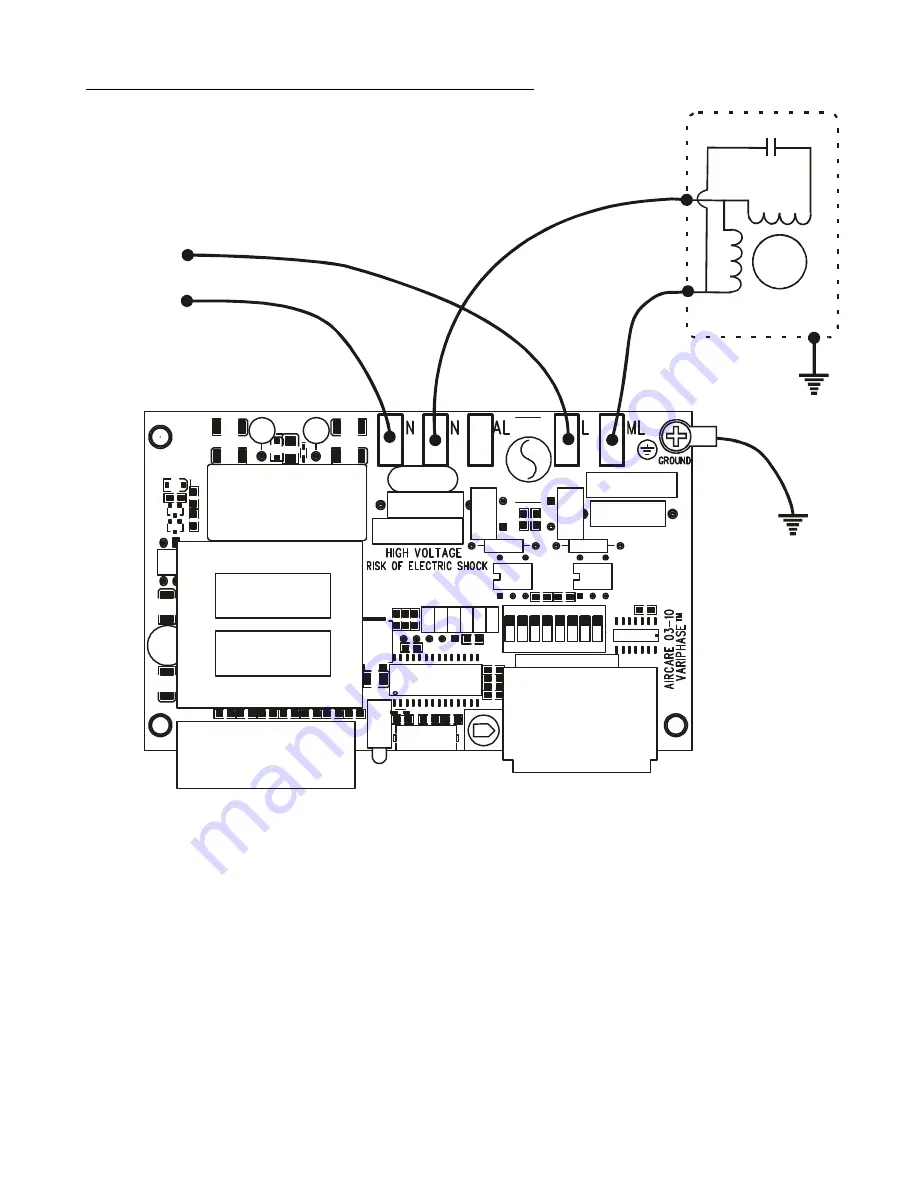
Power Wiring Diagram – 2 wire Motor Connection
J
P
1
2
3
4
5
PSC
Motor
From AC
Line
Neutral
Common
Main
6
Figure 7
Страница 1: ...AirCare VariPhase User Manual ACV1xxx Family of MODBUS Equipped Speed Controls for Fans and Blowers 2 14 Amperes www aircareautomation com Variphase HP Variphase...
Страница 2: ...on 10 Wiring 10 Analog Input Closed Loop Control 11 Overview 11 Configuration 11 Wiring 11 Analog Speed Control with Speed Regulation 12 Overview 12 Configuration 12 LED Indicators 13 Diagnosing Other...
Страница 3: ...air pressure temperature and tachometers In closed loop mode Variphase precisely adjusts motor speed using a PID loop to maintain a set point Installing a distributed network of AirCare controls is si...
Страница 4: ...n model ratings Some Variphase models have specific mounting requirements to achieve max current All parts operate from both 50Hz and 60Hz AC Line 1 7 Amp models should be de rated at 0 1 Amps per 3 C...
Страница 5: ...s such as airflow and orientation affect heat dissipation the installer should ensure that the heatsink does not exceed 70 C worst case Refer to individual datasheets for complete rating information T...
Страница 6: ...gency approved Recognized Component UL508c Power Conversion Equipment CAN CSA C22 2 No 14 M91 UL File number E241590 ACV1021 ACV1022 ACV1033 ACV1041 ACV1042 UL Listed Device UL508c Power Conversion Eq...
Страница 7: ...2 Configure Option Jumpers see Table 2 Set each Variphase with a unique Modbus Address see Page 8 Mount and Enclose Variphase see Page 19 Mount and Enclose Variphase see Page 19 Install Network Wirin...
Страница 8: ...Features Control Terminals LED Indicators RS485 Network Ports Minimum Speed Pot Power and Motor Connections Option Jumpers Address Switches L Bracket Control Terminals LED Indicators RS485 Network Po...
Страница 9: ...tomation Console but other Modbus devices can be used if configured correctly Refer to the Network Specification section of this document for more information Option Jumpers JP1 JP2 JP3 JP4 JP5 JP6 An...
Страница 10: ...non volatile When enabled soft start will occur when the output changes from a stop to start either by increasing the analog input from zero or by the optional enable disable signal Variphase will ram...
Страница 11: ...n App Note 1007 Configuration Install JP1 Remove JP5 Tach Hall Effect Sensor Jumper Wire sensor feedback signal to Control Terminals note signal must not exceed 5 0V Set Bit 3 in MODBUS Register 23 by...
Страница 12: ...to configure closed loop response Adjust Minimum Speed Pot to limit lowest motor voltage Configuration Install JP1 Install JP5 Enable Tach Hall Effect Sensor Jumper Wire tachometer feedback signal to...
Страница 13: ...Faults Most Variphase models have an internal fuse Excessive load current will cause the fuse to fault and the unit will be non functional and non responsive to network communications The fuse is NOT...
Страница 14: ...4 Power Wiring for Variphase 2 8 Amp Models 3 wire motor connection Use this diagram with PSC motors for optimal efficiency and lowest noise JP1 JP2 JP3 JP4 JP5 PSC Motor From AC Line Line Neutral Aux...
Страница 15: ...Revision 1 1 Variphase User Manual Page 15 Power Wiring Diagram 2 wire Motor Connection JP1 JP2 JP3 JP4 JP5 PSC Motor From AC Line Line Neutral Common Main JP6 Figure 7...
Страница 16: ...User Manual Page 16 Power Wiring for Variphase HP Models 3 wire motor connection Use this diagram with PSC motors for optimal efficiency and lowest noise From AC Line Line Neutral PSC Motor Aux Windin...
Страница 17: ...ONTROL MODBUS INPUT 115V 50 60HZ 8A OUTPUT 115V 50 60HZ 8A STAT NET 12V 5V Hall 0V An2 0V An1 VARIPHASE FAN CONTROL MODBUS INPUT 115V 50 60HZ 8A OUTPUT 115V 50 60HZ 8A STAT NET 12V 5V Hall 0V An2 0V A...
Страница 18: ...Motor Speed RPM R 7 Analog 1 Input Level 0 1023 R 8 Minimum Speed Pot Position 0 1023 R 9 System Flags R 10 Default Speed 0 100 R W 11 Firmware Version R 12 Triac Phase Angle R 13 Max Speed 750 3600r...
Страница 19: ...p ACV108x and Variphase 14 Amp ACV114x models have special mounting requirements when operated at or near full load rating Under these conditions they must be securely mounted to an aluminum surface w...