

Quick Installation Guide
RGBW Controller
SD-103 is a security enabled
wireless dimmer, based on
Z-Wave Plus technology. Z-Wave
PlusTM enabled devices
displaying the Z-Wave PlusTM
logo can also be used with it
regardless of the manufacturer,
and can also be used in other
manufacturer’s Z-WaveTM
enabled networks. You can
change the color of your RGBW
LED Strip via the APP and also
control the brightness of the
connected RGBW LED strip.
This dimmer is a transceiver
which is a security enabled
device which based on Z-Wave
Plus technology, and it is fully
compatible with any Z-WaveTM
enabled network. Since SD-103
supports Security Command
Class, it can learn with a Secured
enabled controller to fully utilize
the device.
Before we begin installing the device,
please make sure that the power is off
to avoid electrical shock. When
installing, we suggest that it will be
performed by a qualified and licensed
electrician.
Warnings:
1. The RGBW Controller must be
powered by the same voltage as
the connected light source. I.e.
when controlling 12V LED strip,
the module must be connected to
12V power supply. Similarly, when
controlling 24V RGBW strip, the
RGBW Controller must be
powered by 24V voltage supply.
2. For connection of IN1~IN4, it is
suggested to connect the 4 inputs
individually to the same type of
device. The devices can be as
follows: the momentary switch,
the toggle switch, or the toggle
with memory switch.
3. - First, connect to RGBW strip with
output channel(R, G, B, W)
- Second, connect to the power
supply.
If the device is properly connected,
the RGBW strip will blink once.
Assembling and
Wiring -1
02
Introduction
01
Assembling and
Wiring -2
03
Power the device by
connecting the power circuit
on. Device will automatically
be in inclusion mode.
If device is not in inclusion
mode, press include/exclude
button three times in rapid
succesion
Include RGBW
Controller -1
04
Include RGBW
Controller -2
05
SD-103
Warning:
The RGBW Controller is suggested to
operate in low voltage circuits of
12VDC or 24VDC. Connecting to
higher voltage load may result in the
RGBW Controller damage.
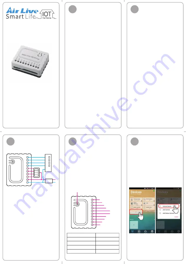
Open AirLive Smart Life APP
Plus in your phone to add the
sensors.
• Go to Devices page and
click ""+"" icon.
• Press Include Device
Figure 2. Connecting toggle switch
Include / Exclude Button
W
B
G
R
IN4
IN3
IN2
IN1
GRD
12/24 VDC
W
B
G
R
12V/24V
12/24VDC
Adapter
12/24VDC - Power supply signal
GND - Power Supply ground signal
IN1 - Switch Input 1
IN2 - Switch Input 2
IN3 - Switch Input 3
IN4 - Switch Input 4
R - Output assigned to IN1
G - Output assigned to IN2
B - Output assigned to IN3
W - Output assigned to IN4