


INSTALLATION INSTRUCTIONS
CAUTION:
MAKE SURE POWER IS SWITCHED OFF AT SERVICE PANEL BEFORE
STARTING INSTALLATION.
SECTION 1
Preparing the Exhaust Fan
1.
Unpack fan from the carton and confirm that all pieces are present. In addition to the
exhaust fan you should have:
1 - Grill
1 - Damper Assembly (attached)
4 - Mounting Rails
1 - Mounting Flange
1 - Fluorescent Lamp
1 - Instruction/Safety Sheet
2.
Choose the location for your fan. To ensure the best air and sound performance, it is
recommended that the length of ducting and the number of elbows be kept to a minimum,
the radius of each elbow be as large as possible
for the installation, and that insulated hard ducting
be used. Larger duct sizes will reduce noise and
airflow restrictions. This fan will require at least 10
”
of clearance in the ceiling or wall, and will mount
through drywall up to 3/4
”
thick.
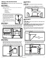
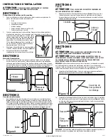
3.
Select the most convenient electrical knockout and
remove using a straight-blade screw driver
(Figure 1).
4.
No additional vibration deadening materials are needed
for this fan.
SECTION 2
New Construction
1.
Install the rails into the mounting channel on the housing. Center the mounting channel in
the slots on the housing, then from inside the housing tighten the mounting channel nuts
so the channel is securely in place. Position the housing next to the joist. Line up housing
so that it will be flush with the finished ceiling. Secure the ends of the rails with screws or
nails (not included) to the joists and slide the housing into the final position
(Figure 2).
SECTION 3
Existing Construction
1.
Set housing in position between the joist and trace an outline onto the ceiling material
(Figure 3).
Set housing aside and cut opening, being careful not to cut or damage any
electrical or other hidden utilities. Install the rails into the mounting channel on the
housing. Center the mounting channel in the slots on the housing, then from inside the
housing tighten the mounting channel nuts so the channel is securely in place. Position
the housing in the previously cut hole so that it is flush with the finished ceiling. Secure
the ends of the rails to the joists
(Figure 2).
www.airkinglimited.com
6728056 Rev. C 5-14
2 of 12
SECTION 4
Ducting
CAUTION:
ALL DUCTING MUST COMPLY WITH LOCAL AND NATIONAL
BUILDING CODES.
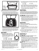
1.
Connect the ducting to the fan’s duct collar
(Figure 4).
Secure in place using tape
or screw clamp. Always duct the fan to the outside through a wall or roof cap. It is
recommended that low restriction termination fittings be used.
SECTION 5
Wiring
CAUTION:
MAKE SURE POWER IS SWITCHED OFF AT SERVICE PANEL BEFORE
STARTING INSTALLATION.
CAUTION:
ALL ELECTRICAL CONNECTIONS MUST BE MADE IN ACCORDANCE
WITH LOCAL CODES, ORDINANCES, OR NATIONAL ELECTRICAL CODE. IF YOU ARE
UNFAMILIAR WITH METHODS OF INSTALLING ELECTRICAL WIRING, SECURE THE
SERVICES OF A QUALIFIED ELECTRICIAN.
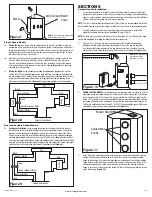
NOTE:
This unit includes a side access panel for wiring that does not require the removal of
the fan’s blower assembly. If you choose to wire the unit from the inside, you will need to
remove the blower assembly and internal wiring compartment. Both methods are equally
effective.
1a. External Wire Compartment: Remove the wire compartment cover screw and place
cover in a secure place
(Figure 5).
1b. Internal Wire Compartment: Using a 7/16
"
socket, remove the two hex nuts holding the
blower assembly in place. Lift up on the assembly and slide it out of the tabs on the
housing
(Figure 6).
Remove the wire compartment cover screw (or screws) and place
the cover in a secure place
(Figure 7).
NOTE:
If the fan motor plug is connected to the fan housing receptacle, unplug so the blower
assembly can be completely removed.
Figure 1
Ducting
Duct
Collar
Figure 4
Figure 5
Screw
Wire
Compartment
Cover
Figure 3
Joist
Housing
Joist
Mounting Rails
Figure 2
Plug
Tabs
Hex Nuts
Figure 6


