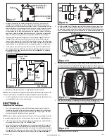


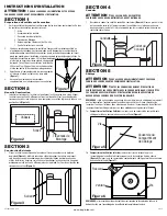


2. For proper fan operation, the humidity sensing fan will require a 3 way switch (not
included). Run wiring between the fan and the switch location. Make sure you leave
enough wiring in each box to make the connections. At the switch box connect the Black
wire from the house to the common terminal of the switch. Connect the black wire from
the fan to one of the switched terminals on the switch. This position will energize the
automatic mode and the fan will energize upon a rise in humidity. Connect the Red wire
from the fan to the other switched terminal on the switch. This position will activate the
Manual On feature and energize the fan. Use approved methods for all connections.
3. To operate the main light and the night light, run wiring from two toggle switches (not
included). At the switch box, connect the Black wire from the house to the common
terminal of each toggle switch. Connect the Yellow wire from the fan to one of the toggle
switches (this is the main light control). Connect the Purple wire from the fan to the other
toggle switch (this is the night light control). Use approved methods for all connections.
4. From where you have chosen to access the fan’s junction box, connect the White wire
from the house to the two White wires from the fan. Connect the ground wire (green or
bare copper) from the house to the Green wire from the fan
(Figure 8)
. Use approved
methods for all connections.
5. Mount the switches and cover using a 3-gang electrical box (not included).
NOTE:
The fan’s receptacle wires might need to be pulled outside compartment for connection.
Only pull the three loose wires outside of compartment. Additional wires will be present.
6. Carefully tuck wires back inside wire compartment and replace wire compartment cover
securing with the screw that was removed earlier.
SECTION 6
Completing the Installation
1. Use a sealant appropriate for contact with the building materials present and for the
temperature requirements of the installation to prevent air leakage from unconditioned
spaces is recommended. If gaps between unit housing and ceiling are great, additional
material (backing rod, ceiling material) may be required.
NOTE:
This fan is rated for direct insulation contact (Type IC) and it is recommended that this fan
be completely covered by insulation in order to reduce heat loss or gain to unconditioned space.
2. If the fan’s blower assembly was removed during the wiring process, reinstall the blower
by reversing the directions in
Step 1b
in
Section 5
Wiring
.
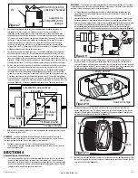
3. Connect the fan wire harness by plugging the 3 pin quick connect end into the receptacle
located on the side of the wire compartment cover. Confirm that the 5 pin quick connect
end is plugged into the receptacle from the blower assembly. Connect the light wire harness
by plugging the 3 pin rectangular quick connect end into the receptacle located at the top of
the wire compartment. These cords will only fit one way into the receptacles
(Figure 9)
.
www.airkinglimited.com
6728023 Rev. G 5-14
3 of 12
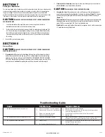
4. Install the included 26 watt fluorescent lamp into the lamp holder by lining up the pins on
the lamp base to the socket of the lamp holder and turning the lamp body clockwise until
the lamp snaps into place and is firmly seated in the lamp holder. Install a 4 watt maximum
type C7 (candelabra base) night light (not included) into the side lamp holder
(Figure 10).
5. Install the reflector onto the grill by placing the slots on the side of the reflector over the
lens clips near the center of the grill. While squeezing the middle of the reflector, slide it so
that the plastic notches rest under the lens clips and the reflector feels secure
(Figure 11).
6. Install the grill (with reflector) by squeezing the two ends of the springs together and installing
them up into the slots on the fan’s housing. Push the grill up into position
(Figure 12).
7. Restore power and test your installation.
Figure 12
Figure 10
Lamp
Lamp Holder
Pin
Night Light
Socket
Slot
Clip
Figure 11
Figure 7
Screw
Wire Compartment
Cover
Humidity Set
Point Knob
Figure 8
Supply from
house
White
Ground
Hot (Yellow)
Hot
(Red)
Hot
(Black)
Hot (Purple)
Figure 9


