


1b.
Internal Wire Compartment:
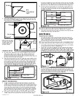
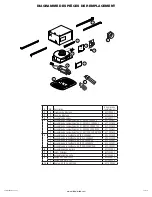
Remove the screws holding the blower assembly in place
and lift assembly out of housing
(Figure 7)
. Remove the wire compartment cover screw
and place the cover in a secure place
(Figure 8).
NOTE:
If the fan motor plug is
connected to the fan housing
receptacle, unplug so the
blower assembly can be
completely removed.
STANDARD MODELS
2b. Run wiring from an approved wall switch carrying the appropriate rating. One neutral
(White), one ground (green or bare copper), and three hot (Black, Purple, Red leads
connected to the switch, one for each function). Secure the electrical wires to the
housing with an approved electrical connector. Make sure you leave enough wiring in the
box to make the connection to the fan’s receptacle.
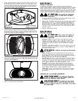
2b. From where you have chosen to access the fan’s junction box, connect the White wire from
the house to the two White wires from the fan. Connect one Hot (Black) wire from the wall
switch to the Black wire from the fan (this is the fan control). Connect second Hot (Purple)
wire from the wall switch to the Purple wire from the fan (this is the night light control).
Connect the third Hot (Red) wire from the wall switch to the Red wire from the fan (this is
the main light control). Connect the ground wire (green or bare copper) from the house to
the Green wire from the fan
(Figure 9)
. Use approved methods for all connections.
HUMIDITY SENSING MODELS
3a. For proper fan operation, the humidity sensing fan will require a 3 way switch (not
included). Run wiring between the fan and the switch location. Make sure you leave
enough wiring in each box to make the connections. At the switch box connect the Black
wire from the house to the common terminal of the switch. Connect the black wire from
the fan to one of the switched terminals on the switch. This position will energize the
automatic mode and the fan will energize upon a rise in humidity. Connect the Red wire
from the fan to the other switched terminal on the switch. This position will activate the
Manual On feature and energize the fan. Use approved methods for all connections.
3b. To operate the main light and the night light, run wiring from two toggle switches (not
included). At the switch box, connect the Black wire from the house to the common
www.airkinglimited.com
210572203 Rev. S 2-17
3 of 12
terminal of each toggle switch. Connect the Yellow wire from the fan to one of the toggle
switches (this is the main light control). Connect the Purple wire from the fan to the other
toggle switch (this is the night light control). Use approved methods for all connections.
3c. From where you have chosen to access the fan’s junction box, connect the White wire
from the house to the two White wires from the fan. Connect the ground wire (green or
bare copper) from the house to the Green wire from the fan
(Figure 10)
. Use approved
methods for all connections.
NOTE:
The fan’s receptacle wires might need to be pulled outside compartment for connection.
Only pull the three loose wires outside of compartment. Additional wires will be present.
4. Carefully tuck wires back inside wire compartment and replace wire compartment cover
securing with the screw that was removed earlier.
SECTION 6
Completing the Installation
1. Use a sealant appropriate for contact with the building materials present and for the
temperature requirements of the installation to prevent air leakage from unconditioned
spaces is recommended. If gaps between unit housing and ceiling are great, additional
material (backing rod, ceiling material) may be required.
NOTE:
This fan is rated for direct insulation contact (Type IC) and it is recommended that this fan
be completely covered by insulation in order to reduce heat loss or gain to unconditioned space.
2. If the fan’s blower assembly was removed during the wiring process, reinstall the blower
by reversing the directions in
Step 1b
in
Section 5
Wiring
.
3. Connect the fan wire harness by plugging the 3 pin quick connect end into the receptacle
located on the side of the wire compartment cover. Confirm that the 5 pin quick connect
end is plugged into the receptacle from the blower assembly. Connect the light wire harness
by plugging the 3 pin rectangular quick connect end into the receptacle located at the top of
the wire compartment. These cords will only fit one way into the receptacles
(Figure 11)
.
4. Install the included lamp into the lamp holder by lining up the pins on the lamp base to the
socket of the lamp holder and turning the lamp body clockwise until the lamp snaps into
place and is firmly seated in the lamp holder. Install a 4 watt maximum type C7 (candelabra
base) night light (not included) into the side lamp holder
(Figure 12).
Figure 6
Screw
Wire
Compartment
Cover
Figure 7
Screws
Plug
Venturi
Figure 8
Screw
Wire
Compartment
Cover
NOTE:
Wire compartment configuration
will be dependent on model.
Figure 11
NOTE:
Wire compartment configuration will be dependent on model.
Figure 12
Lamp
Lamp Holder
Pin
Night Light
Socket
NOTE:
LED lamp shown
Figure 10
Supply from house
Neutral (White)
Ground (Green or Bare)
Fa
n
Neutral (White)
Green
Red
Hot (Black)
Yellow
Purple
Black
Hot (Black)
Hot (Black)
Switch
Switch
Switch
Figure 9
Supply from house
Neutral (White)
Ground (Green or Bare)
Fa
n
Neutral (White)
Green
Hot (Black)
Red
Purple
Black
Switch


