background image

2.

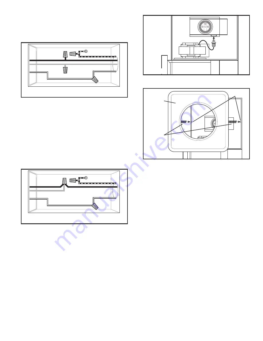
Remove grill from carton and attach springs from grill to posts on
either side of housing 

(Figure 9)

.

5.

Install a 250 watt maximum, R-40 Type A heat lamp (not included)
into the socket and center the grill around the lamp.

NOTE:

 Model AK927 uses 2 - 250 watt maximum R-40, Type A heat lamps.

6.

Restore power and test your installation.

SECTION 7

Use and Care

CAUTION:


MAKE SURE POWER IS SWITCHED OFF AT SERVICE

PANEL BEFORE SERVICING THE UNIT.

CAUTION:


ALLOW LAMP(S) TO COOL BEFORE CLEANING THE

UNIT OR REPLACING THE LAMPS.

1.

Cleaning the Grill:

 Remove heat lamp(s) and detach grill springs

from posts to release grill from housing. Use a mild detergent, such
as dishwashing liquid, and dry with a soft cloth. NEVER USE ANY
ABRASIVE PADS OR SCOURING POWDERS. Completely dry grill
before reinstalling. Refer to instructions in 

Section 6


Completing

the Installation, to reinstall grill.

2.

Cleaning the Fan Assembly:

 Wipe all parts with a dry cloth or gently

vacuum the fan. NEVER IMMERSE ELECTRICAL PARTS IN WATER.

CAUTION:


ALLOW LAMP(S) TO COOL BEFORE REPLACING.

3.

Changing the Heat Lamps:

 Disconnect power to the unit. Unscrew

heat lamp(s) from lamp holder and replace with 250 watt maximum,
R-40, type A heat lamp.

www.airkinglimited.com

210575917 Rev. A 1-06

3 of 8

Figure 9

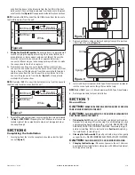
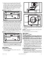
wire from the house to the blue wire from the fan (this is the heat
bulb control). Connect the ground wire from the house to the green
wire from the fan 

(Figure 6)

. Use approved methods for all connections.

NOTE:

 On model AK927 connect the Hot (Blue) wire from the house to

the two Blue wires from the unit.

2.

Wiring Fan/Heat Bulb together:

 Run wiring from an approved wall

switch carrying the appropriate rating. One neutral (white), one
ground (green or bare copper), and one hot (black). Secure the
electrical wires to the housing with an approved electrical
connector. Make sure you leave enough wiring in the box to make
the connection to the fan’s receptacle.

2a. From where you have access to inside the fan’s junction box,

connect the one white wire from the house to the white wire from
the fan. Connect the black wire from the house to both the black
and blue wires from the fan. Connect the ground wire from the
house to the green wire from the fan (

Figure 7)

. Use approved

methods for all connections.

NOTE:

 On model AK927 connect the hot (black) wire from the house to

the black and two blue wires from the unit.

3.

Reinstall the wire compartment cover using the two screws removed
in 

Step 2

 of 

SECTION 1


Preparing the Unit. Make sure all wires are

tucked inside of the compartment and are not being pinched or
showing through.

SECTION 6

Completing the Installation

1.

Insert plug from fan into the receptacle located under the light
socket 

(Figure 8)

.

Figure 6

Ground

Supply from house

White

Hot (Black)

From Fan

Hot (Blue)

Figure 7

Ground

Supply from house

White

Hot (Black)

From Fan

Hot (Blue)

Figure 8

Posts

Springs

Grill

Содержание AK917

Страница 1: ...ey of fuel burning equipment to prevent back drafting Follow the heating equipment manufacturer s guideline and safety standards such as those published by the National Fire Protection Association NFPA and the American Society for Heating Refrigeration and Air ConditioningEngineers ASHRAE andthelocalcodeauthorities CAUTION FOR GENERAL VENTILATING USE ONLY DO NOT USE TO EXHAUST HAZARDOUS OR EXPLOSI...

Страница 2: ...e you have access to inside the fan s junction box connect the white wire from the house to the white wire from the fan Connect one hot black wire from the house to the black wire from the fan this is the fan control Connect the second hot blue INSTALLATION INSTRUCTIONS CAUTION MAKE SURE POWER IS SWITCHED OFF AT SERVICE PANEL BEFORE STARTING INSTALLATION SECTION 1 Preparing the Unit 1 Unpack fan f...

Страница 3: ...lb control Connect the ground wire from the house to the green wirefromthefan Figure6 Useapprovedmethodsforallconnections NOTE On model AK927 connect the Hot Blue wire from the house to the two Blue wires from the unit 2 Wiring Fan Heat Bulb together Run wiring from an approved wall switch carrying the appropriate rating One neutral white one ground green or bare copper and one hot black Secure th...

Страница 4: ...isit our website wwwairkinglimited com Installer _________________________________________________________ Installation Date _________________________________________ Place of Purchase _________________________________________________ Model Number __________________________________________ Qty Description Replacement Part 1 1 AK917 Fan Housing 5S3402080 1 AK927 Fan Housing 5S3402090 2 4 Mounting R...

Страница 5: ...efoulement Suivre les directives du fabricant de l équipement de chauffage et les normes de sécurité telles que celles publiées par la National Fire Protection Association NFPA et de la American Society for Heating Refrigeration and Air Conditioning Engineers ASHRAE et de celles des autorités locales du code AVERTISSEMENT POUR USAGE DE VENTILATION GÉNÉRALE EXCLUSIVEMENT NE PAS UTILISER POUR ÉVACUE...

Страница 6: ...de câble dans la boîte pour permettre le raccordement au réceptacle du ventilateur INSTRUCTIONS D INSTALLATION AVERTISSEMENT VOUS ASSURER QUE L ALIMENTATION EST COUPÉE AU PANNEAU DE SERVICE AVANT DE COMMENCER L INSTALLATION SECTION 1 Préparation du Ventilateur d évacuation 1 Sortir le ventilateur de sa boite et confirmer que toutes les pièces sont présentes En plus du ventilateur d évacuation vous...

Страница 7: ...entilateur celui ci pour le contrôle du ventilateur Raccorder le second fil vivant bleu provenant de la maison au fil bleu du ventilateur celui ci pour le contrôle de la lampe calorique Raccorder le fil de mise à la terre de la maison au fil vert du ventilateur Figure 6 Utiliser des méthodes de raccordement approuvées pour toutes les connexions REMARQUE sur le modèle AK927 connecter le fil vivant ...

Страница 8: ...___________________ Date d installation _______________________________________ Endroit de l achat _________________________________________________ Numéro de modèle _______________________________________ de pièce Qté Description de remplacement 1 1 Cabinet du AK917 5S3402080 1 Cabinet du AK927 5S3402090 2 4 Traverses de Montage 5S1299002 3 1 Collet 5S3402041 4 1 Clapet 5S3402042 5 1 Protection c...

Отзывы: