Doc
No.
FM5640
issue
3
Page
9
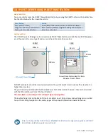
PIN
No.
Cat5e
WIRE
COLOUR
1
White/Orange
2
Orange
3
White/Green
4
Blue
5
White/Blue
6
Green
7
White/Brown
8
Brown
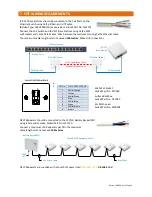
7.
SITE
WIRING
REQUIREMENTS
IP
‐
DECT
Base
Stations
should
be
connected
to
the
PoE
Ports
on
the
Ethernet
Switch
using
Cat5e
Ethernet
U/UTP
cable
(Belden
Type:
1583E.00B100)
or
equivalent,
Aidcall
Part
No.
YW1731.
Connect
the
PoE
Switch
and
IP
‐
DECT
Base
Stations
using
Cat5e
RJ45
wall
sockets
and
Cat5e
Patch
Leads.
Wire
between
the
wall
sockets
using
Cat5e
Ethernet
cable.
The
maximum
cable
length
must
not
exceed
100
metres
.
Make
all
8
connections.
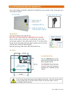
WALL
SOCKET
FROM
REAR
DECT
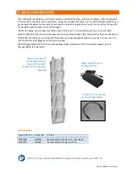
Repeaters
should
be
connected
to
the
12V/2A
Battery
Backed
PSU
using
8
Core
alarm
cable,
Aidcall
Part
No.
YW1730.
Connect
a
maximum
of
6
Repeaters
per
PSU,
the
maximum
cable
length
must
not
exceed
100
metres
.
DECT
Repeaters
are
supplied
with
a
short
RJ11
power
lead;
YELLOW
=
12V
&
BLACK
=
0V
.
4
5
8
7
3
6
2
1
RJ45
Wall
Socket:
Aidcall
Part
No.
P10280
Surface
Backbox:
Aidcall
Part
No.
O15090
2m
Patch
Lead:
Aidcall
Part
No.
W00402
Max
6
DECT
Repeaters
per
PSU
240V
AC
Use
8
Core
Cable
Max
100m
2m
Patch
Lead
2m
Patch
Lead
Cat5e
Cable
(Max
100m)
Make
all
8
connections
Ethernet
Switch
RJ45
Wall
Socket
RJ45
Wall
Socket
IP
‐
DECT
Base
Station
Use
PoE
Ports
Battery
Backed
PSU


