


37
Chapter 3 Motherboard Settings
HA202-PH User's Manual
I2C8SD
A
I2C8SC
L
PSU_SMBDAT_SU
S
PSU_SMBCLK_SU
S
I2C5SD
A
I2C5SC
L
GN
D
FAN12_TAC
H
FAN11_TAC
H
FAN10_TAC
H
FAN9_TAC
H
PWM6
PWM5
LAN4_TRAFFI
C
LAN3_TRAFFI
C
LAN2_TRAFFI
C
LAN1_TRAFFI
C
GN
D
SYS_HEALTH#
HD_LED
UIDLED_OUT
#
GN
D
GN
D
GN
D
GN
D
+5V_AUX
FAN8_TAC
H
FAN7_TAC
H
FAN6_TAC
H
FAN5_TAC
H
FAN4_TAC
H
FAN3_TAC
H
FAN2_TAC
H
FAN1_TAC
H
PWM4
PWM3
PWM2
PWM1
+3.3V_DUAL
+3.3V_DUAL
+3�3V
+3�3V
GN
D
SYS_HEALTH#
HD_LED
+3.3V_DUAL
UID_SW_IN_
N
FP_NMI_BT
N
SW_RST_BTN#
SW_PWR_BTN#
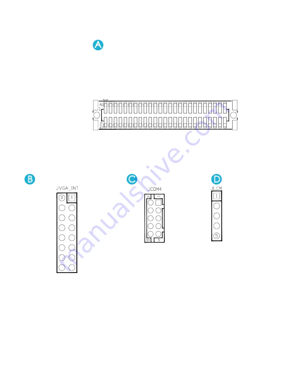
JFRNT/JFRNT_IO
JVGA_INT
GN
D
DACGOA
DDC_DATAO
GN
D
N�C�
AVSYNCO
GN
D
GN
D
FAN1_TAC
H
PWM4
+5V_AUX
FAN8_TACH
FAN7_TACH
FAN6_TACH
FAN5_TACH
FAN4_TACH
FAN3_TACH
FAN2_TACH
FAN1_TACH
PWM4
B
Internal Connectors/Jumpers
DSRB
RTSB
CTSB
RIB
KEY (no pin)
DCDB
RXD
B
TXDB
DTRB
GN
D
JCOM4
C
D
JLCM
SW_PWR_BTN#
SW_RST_BTN#
TXDC
RXD
C
GN
D
Содержание HA202-PH
Страница 1: ...HA202 PH Storage Server Barebone User s Manual UM_HA202 PH_v3_052518...
Страница 43: ...35 Chapter 3 Motherboard Settings HA202 PH User s Manual 3 3 Motherboard Content List...
Страница 59: ...Chapter 5 BMC Configuration Settings HA202 PH User s Manual 51 Step 3 Type in the subnet mask address...
Страница 76: ...Chapter 6 Hardware Specification HA202 PH User s Manual 68 PCIe slim x8 slot CN2 2...
Страница 77: ...Chapter 6 Hardware Specification HA202 PH User s Manual 69 100 x 2 Pin Sametc HSEC8 200p slot CN1 1...
Страница 78: ...Chapter 6 Hardware Specification HA202 PH User s Manual 70 100 x 2 Pin Sametc HSEC8 200p slot CN1 2...
Страница 80: ...Chapter 6 Hardware Specification HA202 PH User s Manual 72 6 6 Drive Slot Map HBA CARD MegaRaid CARD...


