22
Chapter 2. Hardware Setup
FB127-LX User Manual
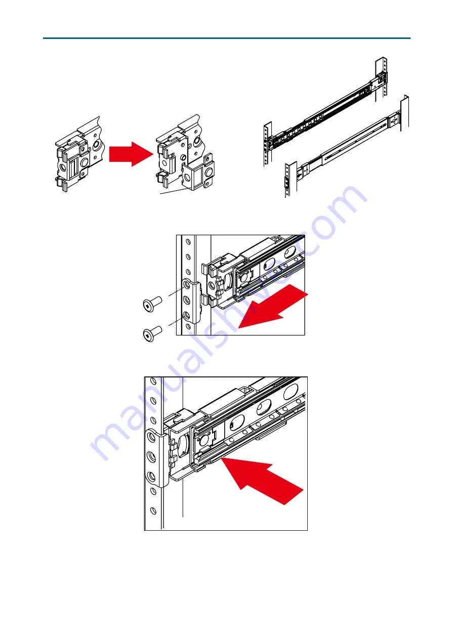
Optional:Remove Metal Spacer for Aluminium Racks
Aligning the Front Bracket with the Mounting Hole.
Push in to assembly the Front Bracket onto the Rack.
Metal Spacer
Страница 1: ...UM_FB127 LX_v1 3_110819 FB127 LX Server Barebone User s Manual...
Страница 2: ...pply Unit Module 15 2 5 Fan Module 16 2 6 Air Duct 17 2 7 OCP Card M 2 Card Module 18 2 8 PCIe Card Module 19 2 9 Solid State Drive Module 20 2 10 Slide Rail 21 Chapter 3 Hardware Settings 25 3 1 Moth...
Страница 3: ...H2O Event Log Config Manager 57 4 4 12 H2oUve Configuration 57 4 5 Security 58 4 5 1 Security 58 4 6 Power 59 4 6 1 Power 59 4 7 Boot 60 4 7 1 Boot 60 4 8 Exit 61 4 8 1 Exit 61 Chapter 5 BMC Configura...
Страница 4: ...History Release Date Version Update Content May 2018 1 User s Manual release to public August 2019 1 1 1 Cover update September 2019 1 2 Motherboard setting update November 2019 1 3 1 Pin definition u...
Страница 5: ...Copyright 2018 AIC Inc All Rights Reserved This document contains proprietary information about AIC products and is not to be disclosed or used except in accordance with applicable agreements...
Страница 6: ...for compliance could void your authority to operate the equipment Disclaimer AIC shall not be liable for technical or editorial errors or omissions contained herein The information provided is provid...
Страница 7: ...lly mount the equipment into the rack in such manner that it won t be hazardous due to uneven mechanical loading This equipment is to be installed for operation in an environment with maximum ambient...
Страница 8: ...ot use liquid or detergent for cleaning The use of a moisture sheet or cloth is recommended for cleaning Module and drive bays must not be empty They must have a dummy cover CAUTION The equipment inte...
Страница 9: ...r provides information for connectors jumpers and LED descriptions These descriptions assist users to configure different settings and functions of the motherboard as well as to confirm the location o...
Страница 10: ...ipping carton Exterior damage to the shipping carton may indicate that the contents of the carton are damaged If any damage is found do not remove the components contact the dealer where the subsystem...
Страница 11: ...console redirection BIOS Boot BIOS Recovery Mode SRIOV iSCSI TPM PCIe Hotplug On board Devices SATA Intel Lewisburg PCH on chip solution 10 x SATA 6 0 Gb s BMC Aspeed AST2500 Advanced PCIe Graphics Re...
Страница 12: ...oteworthy features of the barebone FB127 LX provides immediate and efficient management with Onboard Baseboard Management Controller and greater I O extension Featuring IPMI 2 0 and Aspeed AST2500 Adv...
Страница 13: ...lert LED Drive Activity LED 2 x USB 3 0 Type A port Rear Panel Item Description 1 1600W 1 1 redundant power supply 80 Platinum 2 1 x external DB 15 VGA port 3 2 x GbE RJ45 port 4 1 x10 100M RJ45 port...
Страница 14: ...5 Chapter 1 Product Features FB127 LX User Manual Top View Item Description 10 7 x 40x56 easy swap fans Lynx Serverboard...
Страница 15: ...ure a safe and easy setup you need to prepare before installation a T20 Torx screwdriver ESD wrist strap mat and conductive foam pad CAUTION The pins of the processor socket are vulerable and easily s...
Страница 16: ...ual Processor Socker Assembly The server board includes two processor sockets LGA 3647 supports two Intel Xeon Processor Scalable Family and has a Thermal Design Power TDP of up to 165W on selected mo...
Страница 17: ...PHM is seated over the processor socket assembly the four heat sink torque screws must be secured in the following order as shown below Processor Heat Sink Top View with Screw Tightening Order CAUTIO...
Страница 18: ...re Setup FB127 LX User Manual 2 2 1 Placement 2 2 System Memory JDIMMJ1 JDIMMJ0 JDIMMK1 JDIMMK0 JDIMML1 JDIMML0 JDIMMC0 JDIMMC1 JDIMMB0 JDIMMB1 JDIMMA0 JDIMMA1 JDIMMD1 JDIMMD0 JDIMME1 JDIMME0 JDIMMF1...
Страница 19: ...IMME0 JDIMMF1 JDIMMF0 JDIMMI1 JDIMMH0 JDIMMH1 JDIMMG0 JDIMMG1 JDIMMJ1 JDIMMJ0 JDIMMK1 JDIMMK0 JDIMML1 JDIMML0 CPU0 CPU0 CPU1 CPU1 JDIMMC1 JDIMMB1 JDIMMA0 JDIMMA1 JDIMMD1 JDIMMD0 JDIMME1 JDIMME0 JDIMMF...
Страница 20: ...0 JDIMM_J0 JDIMM_D0 JDIMM_K0 JDIMM_E0 JDIMM_L0 JDIMM_F0 18 DIMMs CPU1 CPU0 JDIMM_I0 JDIMM_C0 JDIMM_I1 JDIMM_C1 JDIMM_H0 JDIMM_B0 JDIMM_H1 JDIMM_B1 JDIMM_G0 JDIMM_A0 JDIMM_G1 JDIMM_A1 JDIMM_J0 JDIMM_D0...
Страница 21: ...DIMM_H0 JDIMM_B0 JDIMM_H1 JDIMM_B1 JDIMM_G0 JDIMM_A0 JDIMM_G1 JDIMM_A1 JDIMM_J0 JDIMM_D0 JDIMM_K1 JDIMM_E1 JDIMM_K0 JDIMM_E0 JDIMM_L1 JDIMM_F1 JDIMM_L0 JDIMM_F0 24 DIMMs CPU1 CPU0 JDIMM_I0 JDIMM_C0 JD...
Страница 22: ...Installation Step 1 Unlock the dimm socket by pressing the retaining clips outward Step 2 Insert the memory module into the slot Make sure that the dimm notch is accurately positioned Step 3 Close th...
Страница 23: ...r 2 Hardware Setup FB127 LX User Manual Loosen the screws x 2 on the top cover Push the cover towards the rear panel and lift upward 2 3 Top Cover This information is provided for professional technic...
Страница 24: ...release the module Pull the handle to remove the module out of the chassis Push the replaced power supply unit into the chassis Ensure that the module is hooked into the cage This information is prov...
Страница 25: ...and connectors from the fan Extract the fan by carefully dislodging the rubber connectors on the fan from the securing bracket Insert the new fan into the chassis by verifying the alignment of the ru...
Страница 26: ...17 Chapter 2 Hardware Setup FB127 LX User Manual Position the airduck on top of the heatsink and secure the screw 2 6 Air Duct This information is provided for professional technicians only...
Страница 27: ...the OCP card bracket and pull it out of the chassis Insert a new OCP card M 2 card into the bracket Insert the bracket into the chassis Secure the screws to complete installation This information is...
Страница 28: ...from the chassis Pull the PCIe card from the bracket Insert a new PCIe card into the PCIe bracket Verify that the gold finger is properly aligned with the PCIe slot Secure the screws on the bracket t...
Страница 29: ...User Manual Press the release button the tray lever to loosen the lever Pull the tray lever outward completely Pull the tray out of the system This information is provided for professional technician...
Страница 30: ...Hardware Setup FB127 LX User Manual 2 10 Slide Rail Pull on the Front Release to unlock the inner channel from the Slide Assembly Release the Detent Lock and push Middle Channel inwards to retract Mi...
Страница 31: ...pter 2 Hardware Setup FB127 LX User Manual Optional Remove Metal Spacer for Aluminium Racks Aligning the Front Bracket with the Mounting Hole Push in to assembly the Front Bracket onto the Rack Metal...
Страница 32: ...2 Hardware Setup FB127 LX User Manual Now the bracket is fixed onto the Rack Optional M6x10L screws are to secure the rails with posts if needed Refer to step 3 and 4 to assemble the End Bracket onto...
Страница 33: ...24 Chapter 2 Hardware Setup FB127 LX User Manual Assemble the inner channel onto the chassis using thescrews provided Push the chassis with inner channels into Slide to complete Rack Installation...
Страница 34: ...r Card CONN C CONN A CONN B CONN B CONN A PCI Express x 16 PCI Express x 16 Port1a IOU0 Port1a IOU0 P C I E xpress x 16 P C I E xpress x 16 Steering Resistors P C I E xpress x 16 PL 2303HXD Port3aIOU2...
Страница 35: ..._INT 8a 8b Front I O USB Header JUSB_INT1 JUSB_INT2 30 AUX Power Header JPWR_AUX 9 Front I O USB 2 0 Header JUSB20 31 VRM SMB Header JSMB_VR 10 OCuLink Connector JSYS_EXT 32 PCH GPIO Header JPCH_GPIO...
Страница 36: ...SKILL Disable Jumper J14 J17 I Flash Descriptor Security override Jumper J3 C PS_ON Enable Jumper J18 J NTB Configuration Jumper JNTB D1 D2 SATA Power Header J12 J13 K Clear CMOS Jumper JCMOS E CPU0 C...
Страница 37: ...220 76 78 1 145 146 221 222 77 79 287 288 143 144 223 220 76 78 1 145 146 221 222 77 79 287 288 143 144 223 220 76 78 1 145 146 221 222 77 79 287 288 143 144 24 23 2 1 24 23 1 1 5 2 68 58 2 74 64 32...
Страница 38: ...wer Header JPWR1 JPWR2 JPWR3 JPWR4 2 Power Supply Connector JPWR5 3 Power Supply Header JPMBUS_PDB 4 PMBus Header JPMBUS 5a 5h Fan Connector J19 J20 J23 J25 J26 J27 J28 1 SMB_PMBUS_CLK 2 SMB_PMBUS_DAT...
Страница 39: ...2 8a Front I O USB Header JUSB_INT1 JUSB_INT2 8b Front I O USB Header JUSB_INT2 1 GND 2 12V 3 TACH 4 PWM PCH_FP_USB3_RX_N5 PCH_FP_USB3_RX_P5 PCH_FP_USB3_TX_N5 PCH_FP_USB3_TX_P5 PCH_FP_USB2_N7 PCH_FP_U...
Страница 40: ...dware Settings FB127 LX User Manual 9 Front I O USB 2 0 Header JUSB20 10 OCuLink Connector JSYS_EXT 11a BMC GPIO Header JBMC_GPIO1 11b BMC GPIO Header JBMC_GPIO2 GPIOP3 2 1 GND GPIOP2 4 3 GPIOI3 GPION...
Страница 41: ...32 FB127 LX User Manual Chapter 3 Hardware Settings 12 Front Panel Header JFRNT_SSI 13 PCH SGPIO Header JSGPIO 14 PCH SSGPIO JSSGPIO 18 LCM Header JLCM 1 SW_PWR_BTN 2 SW_RST_BTN 3 TXDC 4 RXDC 5 GND...
Страница 42: ...JBMC_I2C10 29 VGA Header JVGA_INT 30 AUX Power Header JPWR_AUX 1 5V 2 BMC_BUZZER 1 I2C1SDA 2 GND 3 I2C1SCL 4 N C 1 I2C10SCL 2 I2C10SDA 3 GND DACROA 2 1 GND N C 4 3 DACGOA GND 6 5 DDC_DATAO DACBOA 8 7...
Страница 43: ...4 PCH_GPP_C10 CPU1_HP_I2C_CLK 2 1 CPU0_HP_I2C_CLK CPU1_HP_I2C_DAT 4 3 CPU10_HP_I2C_DAT GND 6 5 3 3V GND 1 2 SMB_HFI0CPU0_LVC2_SCL FM_MODPRST_HFI0_CPU0_LVT2_N 3 4 SMB_HFI0CPU0_LVC2_SDA LED_HFI0_CPU0_N...
Страница 44: ...18 12V PMBUS_SDA A19 B19 PMBUS_A0 PMBUS_SCL A20 B20 PMBUS_A1 PS_ON A21 B21 12V_AUX ALERT A22 B22 CR_BUS_N SENSE A23 B23 12LS SENSE A24 B24 PSKILL PW_OK A25 B25 COM_BUS GND 1 2 SMB_HFI0CPU1_LVC2_SCL FM...
Страница 45: ...iguration Jumper JPG_LOCK JPG_LOCK Setting Short Enable Open Disable Defualt F Chassis Intruder JINTRUDER JINTRUDER Setting Short Case Open Open Enable Defualt G BMC Reset Jumper JBMC_RST JBMC_RST Set...
Страница 46: ...l events fan failures NMI etc Off No critical failure is detected System ID Blue ID activity is detected Off No ID activity is detected NOTE The latest version of this product uses attention button mo...
Страница 47: ...Yellow Resume Well Reset is on OFF Resume Well Reset is off UID LED Blue UID activity is detected Off UID activity is not detected NGFF LED Blue Blinking NGFF activity is detected Off NGFF activity is...
Страница 48: ...JPWR2 JPWR_MB1 JPWR_MB2 JPWR1 Thermal sensor J4 J5 J6 J7 JPIC32_ICE JPICE32_USB JPMBUS1 JPMBUS J1 J2 J3 JMB_ID_A JMB_ID_B JFRONT E1 F1 G1 H1 E2 F2 G2 H2 A1 B1 C1 D1 A2 B2 C2 D2 SW1 SW2 J1 K1 J2 K2 3 3...
Страница 49: ...2 GND 9 12V 1 GND 8 12V PMBUS Connector JPMBUS JPMBUS1 Pin Description 1 PW_SCL 2 PW_SDA 3 NC 4 GND 5 NC Power Input Connector JPWR1 Pin Description Pin Description 7 PSU_ON_N 14 PWROK_PSU 6 GND 13 5V...
Страница 50: ...PIC_SDA5 21 3VSTBY 22 PIC_SCL5 19 B_MB_ID_BTN_N 20 GND 17 GND 18 GND 15 NC 16 B_MB_ALERT_LED 13 3VSTBY 14 B_MB_ID_LED 11 NC 12 A_MB_ALERT_LED 9 3VSTBY 10 A_MB_ID_LED 7 3VSTBY 8 B_MB_PWR_LED 5 A_MB_ID...
Страница 51: ...42 FB127 LX User Manual Chapter 3 Hardware Settings Bootloader mode switch SW1 GND GND Boot loader SW Default High Active low MCU PIC32 Reset SW2 GND GND MCLR Default High Active low...
Страница 52: ...LED2035 Green On Drive status normal No HDD activity Blinking Drive activity 4Hz Off Drive is not present Red On Drive fault status Blinking Re build status 1Hz Off Normal PIC32 MCU Bootloader LED LE...
Страница 53: ...he details of BIOS menu Please be noted that the BIOS menu are continually changing due to the BIOS updating The BIOS menu provided are the most updated ones when this manual is written The default va...
Страница 54: ...ter to access the option screen Menu Description Main Displays basic system information and date time Advanced Allows configuration of advanced system settings Security Sets passwords and security fun...
Страница 55: ...46 FB127 LX User Manual Chapter 4 BIOS Configuration Settings Main Option Key 4 3 1 Main Main System time Configures the current time System date Configures the current date 4 3 Main...
Страница 56: ...deo Configuration Display Mode Plug In First On Board First 4 4 3 OEMBoard Function OEMBOARD Function Messiah Function SMBIOS Updated SMBIOS Updated Auto By Utility SMBIOS TO BMC Redfish Write SMBIOS...
Страница 57: ...16T 4T 1T MMIO High Granularity Size 1G 4G 16G 64G 256G 1024G Serial Debug Message Level Disable Minimum Normal Maximum UPI Configuration UPI General Configuration UPI Status Link Speed Mode Slow Fas...
Страница 58: ...rror Partial Mirror Mode 1LM Disable UEFI ARM Mirror Enable Disable Memory Rank Sparing Enable Disable Correctable Error Threshold Min 0x0 Max 0x7fff SDDC Plus One Enable Disable ADDDC Sparing Enable...
Страница 59: ...CC Correctable error Auto Enable Disable NGN ECC Write Check Auto Enable Disable NGN ECC Write Retry Flow Exit Auto Enable Disable C A Parity Enable Auto Enable Disable High Address Region Auto Bit Po...
Страница 60: ...ms DMA Enable Disable No Snoop Enable Disable Intel VT for Directed I O VT d Intel VT for Directed I O VT d Enable Disable Interrupt Remapping Enable Disable PassThrough DMA Enable Disable ATS Enable...
Страница 61: ...ode Enable Disable CPU Flex Ratio Override Enable Disable Perf P Limit Differential Min 0 Max 7 1 Perf P Limit Clip Min 0 Max 31 31 Perf P Limit Threshold Min 0 Max 31 15 Perf P Limit Enable Disable H...
Страница 62: ...GC_ CLK_GATE_ DISABLE Enable Disable IIO2_PKGC_ CLK_GATE_ DISABLE Enable Disable UPI01_PKGC_ CLK_GATE_ DISABLE Enable Disable UPI23_PKGC_ CLK_GATE_ DISABLE Enable Disable MC1 PKGC CLK GATE DISABLE Ena...
Страница 63: ...Error Host Reset Warning 0 1 None Enable Pre DramInit Done ME Reset 0 1 None HMRFPO_LOCK Message Enable Disable HMRFPO_ENABLE Message Enable Disable END_OF_POST Message Enable Disable HECI 1 Enable HE...
Страница 64: ...ressive Link Power Management Enable Disable Port 0 5 Enable Disable sSATA Port 0 5 DevSlp Enable Disable Hot Plug Enable Disable Configure as eSATA Enable Disable Spin Up Device Enable Disable sSATA...
Страница 65: ...DR List Support Enable Disable 4 4 9 APEI Configuration APEI Configuration ACPI Platform Error Interface APEI Support Enable Disable APEI Error Injection MEMORY_CE MEMORY_UE_ NON_FATAL MEMORY_UE_ FATA...
Страница 66: ...EBUG_WARN Enable Disable DEBUG_LOAD Enable Disable DEBUG_FS Enable Disable DEBUG_INFO Enable Disable DEBUG_ DISPATCH Enable Disable DEBUG_ VARIABLE Enable Disable DEBUG_BM Enable Disable DEBUG_BLKIO E...
Страница 67: ...ce Not Detected TPM 1 2 TPM 2 0 TPM Active PCR Hash Algorithm SHA1 SHA256 TPM Hardware Supported Hash Algorithm SHA1 SHA256 TrEE Protocol Version 1 0 1 1 TPM Availability Available Hidden TPM Operatio...
Страница 68: ...59 Chapter 4 BIOS Configuration Settings FB127 LX User Manual Power Option Key 4 6 1 Power Power Wake on PME Enable Disable 4 6 Power...
Страница 69: ...EFI IPv6 Legacy Add Boot Options First Last Auto ACPI Selection Acpi1 0B Acpi3 0 Acpi4 0 Acpi5 0 Acpi6 0 Acpi6 1 USB Boot Enable Disable EFI Device First Enable Disable Timeout Min 0 Max 10 3 Automati...
Страница 70: ...your changes without exiting the system Exit Discarding Changes Discard your changes when existing the system Load Optimal Defaults Load optimal default items Load Custom Defaults Resets the BIOS sett...
Страница 71: ...setting The IP address is configurable Step 1 Open the browser then type in the default BMC IP address 192 168 22 108 Step 2 Use the default user name and password for first time BMC WEB GUI login Fie...
Страница 72: ...ports page monitors and reports on the status of IPMI event Settings The Settings page allows you to configure various basic settings such as date time KMV Mouse Services and ect Remote Control The Re...
Страница 73: ...d Operator All BMC commands are allowed except for the configuration commands that can change the behavior of the out of hand interfaces Administrator All BMC commands are allowed No access Login acce...
Страница 74: ...hboord page displays device system and network information Click Dashboard on the menu bar to view the overall information of the server 5 2 4 Sensor The Sensor page displays the status and records on...
Страница 75: ...Information Board Information and Product Information of the FRU device Click FRU Information on the menu bar to view the details of the selected device 5 2 6 Logs and Reports The System Inventory pa...
Страница 76: ...on Settings General Settings VMedia Instance Settings Remote Session Network Settings Network Settings Network Link Configuration DNS Configuration Sideband Interface NC SI Platform Event Filter Event...
Страница 77: ...68 Chapter 5 BMC Configuration Settings FB127 LX User Manual 5 2 8 Remote Control The Remote Control page displays the configuration for power control and remote KVM Launch KVM...
Страница 78: ...ttings Procedure To Start KVM Step 1 Click Start KVM to start the H5Viewer video redirection Step 2 Click Browse to select CD Image Step 3 Click Start Media to redirect the selected CD image file to t...
Страница 79: ...Mode This option handles mouse emulation from local window to remote screen using either of the two methods Only Administrator has the right to configure this option Absolute mouse mode The absolute...
Страница 80: ...epressed the CTRL ALT and DEL keys down simultaneously on the server that you are redirecting Left Windows This menu item can be used to act as the left side WIN key when in Console Redirection You ca...
Страница 81: ...options of Power Control are given below Power Off To immediately power off the server Power On To power on the server Power Cycle This option will first power off and then reboot the system cold boo...
Страница 82: ...ly Firmware Update This wizard takes you through the process of firmware upgradation A reset of the box will automatically follow if the upgrade is completed or cancelled An option to Preserve All Con...
Страница 83: ...ation Settings FB127 LX User Manual 5 2 11 Sign out To log out of the BMC Method 1 Click Sign out from the menu bar The Logout dialog box will pop out Method 2 Click the root quick button on the top r...
Страница 84: ...om tw Support Email support ru aicipc com tw North California United States Address 48531 Warm Springs Boulvard Suite 404 Fremont CA 94539 United States Tel 1 510 573 6730 Fax 1 510 573 6729 Sales Ema...