background image

10

INSTALLATION INSTRUCTIONS

GROUND

HIGH LIMIT SWITCH

THERMOSTAT

ELEMENT

THERMOSTAT

ELEMENT

THERMOSTAT

ELEMENT

THERMOSTAT

ELEMENT

HIGH LIMIT SWITCH

MISE À LA TERRE

INTERRUPTEUR

HAUTE TEMPÉRATURE

INTERRUPTEUR

HAUTE TEMPÉRATURE

THERMOSTAT

THERMOSTAT

ÉLÉMENT

ÉLÉMENT

ÉLÉMENT

ÉLÉMENT

THERMOSTAT

THERMOSTAT

THERMOSTAT

THERMOSTAT

THERMOSTAT

THERMOSTAT

GROUND/

MISE À LA TERRE

HIGH LIMIT SWITCH/

INTERRUPTEUR

HAUTE TEMPÉRATURE

HIGH LIMIT SWITCH/

INTERRUPTEUR

HAUTE TEMPÉRATURE

ELEMENT/ÉLÉMENT

ELEMENT/ÉLÉMENT

ELEMENT/ÉLÉMENT

ELEMENT/ÉLÉMENT

POWER DISTRIBUTION BLOCK

GROUND

HIGH LIMIT SWITCH

THERMOSTAT

ELEMENT

THERMOSTAT

ELEMENT

THERMOSTAT

ELEMENT

THERMOSTAT

ELEMENT

HIGH LIMIT SWITCH

MISE À LA TERRE

INTERRUPTEUR

HAUTE TEMPÉRATURE

INTERRUPTEUR

HAUTE TEMPÉRATURE

THERMOSTAT

THERMOSTAT

ÉLÉMENT

ÉLÉMENT

ÉLÉMENT

ÉLÉMENT

THERMOSTAT

THERMOSTAT

GROUND/

MISE À LA TERRE

HIGH LIMIT SWITCH/

INTERRUPTEUR

HAUTE TEMPÉRATURE

HIGH LIMIT SWITCH/

INTERRUPTEUR

HAUTE TEMPÉRATURE

THERMOSTAT

THERMOSTAT

ELEMENT/ÉLÉMENT

ELEMENT/ÉLÉMENT

ELEMENT/ÉLÉMENT

ELEMENT/ÉLÉMENT

THERMOSTAT

THERMOSTAT

Ancien Nom : Commer_Wiring_05

Nouveau Nom : DF-Comm-50-80-120G-4Ele

Ancien Nom : Commer_Wiring_05

Nouveau Nom : DF-Comm-50-80-120G-4Ele

Ancien Nom : Commer_Wiring_05

Nouveau Nom : DF-Comm-50-80-120G-4Ele

POWER DISTRIBUTION BLOCK/BORNIER DE DISTRIBUTION

BORNIER DE DISTRIBUTION

POWER DISTRIBUTION BLOCK

POWER DISTRIBUTION BLOCK/BORNIER DE DISTRIBUTION

BORNIER DE DISTRIBUTION

RED

RED

RED

RED

RED

RED

BLACK

BLACK

BLACK

BLACK

BLACK

BLACK

NOIR

NOIR

NOIR

NOIR

BLACK/NOIR

BLACK/NOIR

BLACK/NOIR

BLACK/NOIR

BLACK

BLACK

ROUGE

ROUGE

ROUGE

ROUGE

ROUGE

ROUGE

NOIR

NOIR

NOIR

NOIR

RED/ROUGE

RED/ROUGE

RED/ROUGE

RED/ROUGE

RED/ROUGE

RED/ROUGE

BLACK/NOIR

BLACK/NOIR

BLACK/NOIR

BLACK/NOIR

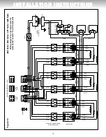
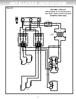
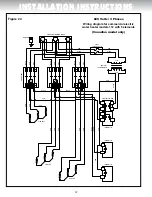
figure 12

208 Volts / 240 Volts / 277 Volts / 480 Volts 

wiring diagram 

for commercial electric water heater 

models 105, 108 & 112 

with 4 elements

Содержание 105

Страница 1: ...he water heater rating plate DO NOT CONNECT the power supply wiring to anywhere other than the power distribution block in elec trical junction box of the water heater DO NOT TURN ON the power to the water heater unless it is completely filled with water DO NOT DRAIN the water heater unless the power to the water heater has been turned OFF DO NOT STORE or use gasoline or other flammable vapours an...

Страница 2: ...rts you to potential hazards that can kill or hurt you and others All safety messages will follow the safety alert symbol and either the word DANGER or WARNING Serious injury or death can occur if you do not follow the instructions immediately Serious injury or death can occur if you do not follow the instructions Before proceeding with the installation instructions 1 Inspect the water heater and ...

Страница 3: ... are twelve 12 inches 30 5 cm from the top and thirty 30 inches 76 2 cm in front of the unit Sooner or later all water heaters leak The manufacturer based on national building codes has given the necessary advice to prevent damage to the building Under no cir cumstances is the manufacturer to be held liable for any water damage in connection with this water heater Should this water heater be insta...

Страница 4: ... Canada and ANSI Z21 22 in the United States is supplied with the water heater and MUST BE installed by the installer The relief valve should never be plugged or removed from the opening marked for it on the water heater If this relief valve should need to be replaced use only a new tempera ture and pressure relief valve Never install an old or existing relief valve as it may be damaged or inadequ...

Страница 5: ...ied service technician must be called to have the system checked and the problem corrected Filling the Water Heater DANGER WARNING CAUTION AVERTISSEMENT ATTENTION NEVER operate the water heater unless it is completely filled with water Failure to follow this instruction can result in premature failure of the water heater and its component parts that is not covered by the warranty Check that all of...

Страница 6: ...net d arrêt manuel Figure 6 All Bronze Circulating Pump Thermometer Check Valve Tank Temperature Control ONE TEMPERATURE ONE WATER HEATER STORAGE TANK FORCED CIRCULATION WITHOUT BUILDING RECIRCULATION HOT WATER OUTLET COLD WATER INLET Manual shut Off Valve Temperature and Pressure Relief Valve Overflue Tube Flow Regulating Plug Cock Thermal Expansion Tank Union Union Union Union Union Pompe circul...

Страница 7: ...Valve Tank Temperature control HOT WATER OUTLET Thermometer Thermal Expansion Tank COLD WATER SUPPLY Thermometer TWO HEATERS WITH STORAGE TANK WITH OR WITHOUT BUILDING CIRCULATION Temperature and Pressure Relief Valve Overflue Tube Manual shut off Valve Union NOTE Must Be Identical Size Water Heaters Union Union Union Union Union Union RÉSERVOIR D ENTREPOSAGE CHAUFFE EAU 2 CHAUFFE EAU 1 Pompe circ...

Страница 8: ...ON STORAGE TANK HEATER 1 HEATER 2 HEATER 3 HOT WATER OUTLET COLD WATER SUPPLY Temperature and Pressure Relief Valve Overflue Tube Union Manual shut Off Valve NOTE Must Be Identical Size Water Heaters Union Union Union Union Union Union Union Union Robinet régulateur de débit Réservoir d expansion thermique Thermomètre Clapet de retenue Pompe circulatrice en bronze Contrôle de température de la cuv...

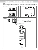
Страница 9: ...ltage on the rating plate of the water heater 480V 277V 240V 208V 0V PRIMARY X1 X2 0V 120V Figure 10B Figure 10A POWER DISTRIBUTION BLOCK GROUND HIGH LIMIT SWITCH THERMOSTAT THERMOSTAT ELEMENT ELEMENT RED RED RED BLACK BLACK BLACK BLACK Figure 11 208 Volts 240 Volts 277 Volts 480 Volts Wiring diagram for commercial electric water heater models 105 108 112 with 2 elements PRIMARY 600V 240V PRIMAIRE...

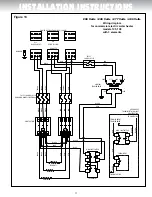
Страница 10: ...OSTAT ELEMENT THERMOSTAT ELEMENT HIGH LIMIT SWITCH Ancien Nom Commer_Wiring_05 Nouveau Nom DF Comm 50 80 120G 4Ele RED RED RED RED RED RED BLACK BLACK BLACK BLACK BLACK BLACK BLACK BLACK Figure 12 208 Volts 240 Volts 277 Volts 480 Volts Wiring diagram for commercial electric water heater models 105 108 112 with 4 elements ...

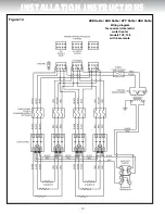
Страница 11: ...SFORMER FUSES 30 AMP CLASS G CANADIAN MODELS OPTIONAL CONTROL TRANSFORMER 480V 0V 120V 277V 240V 208V 0V FUSES 3 AMP CLASS G RED BLACK BLACK BLUE BLACK BLACK BLACK RED RED YELLOW BLUE BLUE BLACK BLACK RED RED BLACK RED BLACK BLACK RED RED BLACK RED RED BLACK BLACK RED BLUE RED RED BLACK BLACK INSTALLATION INSTRUCTIONS Figure 13 208 Volts 240 Volts 277 Volts 480 Volts Wiring diagram for commercial ...

Страница 12: ...12 INSTALLATION INSTRUCTIONS Figure 14 208 Volts 240 Volts 277 Volts 480 Volts Wiring diagram for commercial electric water heater models 105 108 with 6 elements ...

Страница 13: ... BLACK RED BLACK RED BLACK RED BLACK RED BLACK RED BLACK RED BLACK BLACK BLACK RED RED YELLOW RED RED YELLOW RED RED YELLOW BLUE BLACK BLACK BLUE BLACK BLACK BLUE RED RED RED BLACK BLACK BLACK RED RED RED BLACK BLACK BLACK RED RED RED BLACK BLACK BLACK RED RED RED BLACK BLACK BLACK RED RED RED BLACK BLACK BLACK RED RED RED BLACK BLACK BLACK INSTALLATION INSTRUCTIONS Figure 15 208 Volts 240 Volts 2...

Страница 14: ...V 277V 240V 208V 0V 0V CONTROL TRANSFORMER POWER DISTRIBUTION BLOCK 1 PHASE RED RED YELLOW BLACK RED BLACK BLACK BLUE RED RED BLACK BLACK RED BLACK RED RED BLACK BLACK RED BLACK BLUE BLUE BLACK BLACK BLACK RED BLACK RED INSTALLATION INSTRUCTIONS Figure 16 208 Volts 240 Volts 277 Volts 480 Volts Wiring diagram for commercial electric water heater models 112 with 3 elements ...

Страница 15: ...STRIBUTION BLOCK 1 PHASE BLACK BLACK RED RED BLACK BLACK BLACK BLACK RED RED RED YELLOW BLACK BLACK BLUE RED RED YELLOW BLACK BLACK BLUE RED RED RED BLACK BLACK RED BLACK RED RED BLACK BLACK BLACK RED BLACK RED RED BLACK BLACK RED BLACK RED RED BLACK BLACK RED BLACK BLUE BLUE BLACK RED RED Figure 17 INSTALLATION INSTRUCTIONS 208 Volts 240 Volts 277 Volts 480 Volts Wiring diagram for commercial ele...

Страница 16: ...0G 9Ele RED BLACK BLACK BLACK BLACK BLACK BLACK RED BLACK BLACK BLACK BLACK BLACK BLACK BLACK BLACK BLACK BLACK BLACK BLACK BLACK BLACK BLACK BLACK BLACK BLACK BLACK BLACK BLACK BLACK BLACK BLACK BLACK BLUE BLUE BLUE BLUE BLUE RED YELLOW YELLOW RED RED RED RED RED RED RED RED RED RED RED RED RED RED RED RED RED RED RED RED RED RED RED YELLOW RED RED BLACK YELLOW YELLOW RED RED RED BLACK Figure 18 ...

Страница 17: ...TION HIGH LIMIT SWITCH THERMOSTAT TO CONTACTOR TO CONTACTOR FROM CURRENT TRANSFORMER POWER DISTRIBUTION BLOCK BLACK RED BLUE RED RED BLACK BLACK RED RED BLACK BLACK RED RED BLUE Ancien Nom Commer_50 80_102 Nouveau Nom DF Comm 50 80 600V 3Ele RED BLACK BLACK RED BLUE 600 Volts 3 Phases Wiring diagram for commercial electric water heater models 105 108 with 3 elements Canadian model only ...

Страница 18: ...ROUND ELEMENTS ELEMENTS CONTACTORS BLACK RED RED RED RED BLUE BLACK BLACK BLACK BLACK RED RED RED RED RED RED RED BLACK RED BLACK RED Ancien Nom Commer_50 80_101 Nouveau Nom DF Comm 50 80 600V 6Ele THERMOSTAT BLUE 600 Volts 3 Phases Wiring diagram for commercial electric water heater models 105 108 with 6 elements Canadian model only ...

Страница 19: ...LEMENTS ELEMENTS ELEMENTS CONTACTORS POWER DISTRIBUTION BLOCK RED BLACK RED RED RED RED BLACK RED BLACK RED RED RED RED BLUE BLUE BLUE BLACK BLACK BLACK BLACK RED RED RED BLACK RED RED RED RED RED RED BLACK 600 Volts 3 Phases Wiring diagram for commercial electric water heater models 105 108 with 9 elements Canadian model only ...

Страница 20: ...SES 3 AMP CLASS G CONTROL TRANSFORMER THERMOSTAT ELEMENTS CONTACTOR POWER DISTRIBUTION BLOCK RED RED RED RED BLUE RED RED RED BLACK BLACK BLACK BLUE BLACK BLACK 600 Volts 3 Phases Wiring diagram for commercial electric water heater models 112 with 3 elements Canadian model only ...

Страница 21: ...GROUND THERMOSTAT THERMOSTAT CONTACTORS ELEMENTS ELEMENTS POWER DISTRIBUTION BLOCK BLACK RED BLACK BLACK BLACK BLUE RED RED RED BLACK RED BLACK BLUE RED RED RED RED RED RED BLUE RED BLACK RED 600 Volts 3 Phases Wiring diagram for commercial electric water heater models 112 with 6 elements Canadian model only ...

Страница 22: ...EMENTS ELEMENTS ELEMENTS CONTACTORS POWER DISTRIBUTION BLOCK RED BLACK 600V 240V RED RED RED RED BLACK RED BLACK BLACK BLACK BLACK BLUE BLUE BLUE BLUE RED RED RED RED BLACK BLACK BLACK YELLOW RED RED RED RED RED RED RED RED 600 Volts 3 Phases Wiring diagram for commercial electric water heater models 112 with 9 elements Canadian model only ...

Страница 23: ...ing power to terminal block L1 and L2 Surface mount thermostat Single phase to three 3 phases See Figure 26 Figure 26 BLACK RED BLUE YELLOW Single Phase L1 L2 Power distribution block 1 Disconnect all blue from terminal L1 on the distribution block 2 Disconnect all yellow wires from terminal L2 3 Reconnect all blue and yellow wires to terminal L3 4 Connect incoming power to terminal block L1 L2 an...

Страница 24: ...f elements in the water heater to be converted 4th digit of model number on the rating plate see page 23 2 Find the Desired total input kW in Table 2 that matches the number of elements 3 Then move across the Table 2 on the same row to the Desired Voltage column The appropriate Conversion Kit part number will be the one where the Desired total input row intersects the Desired Voltage column DANGER...

Страница 25: ...TISSEMENT ATTENTION DO NOT turn ON the power to this water heater if It is not completely filled with water The power supply voltage does not match the voltage listed on the rating plate Gasoline or other flammable vapours and liquids have been stored in the vicinity of the water heater Failure to follow these instructions can result in property dam age personal injury or death Do not open the ele...

Страница 26: ...he red reset button on the high limit switch 4 Replace the insulation and close the element access panel before turning ON the power to the water heater Water Temperature Regulation The higher the setting the greater the risk of scalding Hot water can cause third degree burns in less than one 1 second at 160 F 71 C in five 5 seconds at 140 F 60 C and in thirty 30 seconds at 130 F 54 C In household...

Страница 27: ... 11 to 24 7 Set the thermostat to the desired temperature see Water Temperature Regulation page 26 8 Replace the insulation and close the element access panel before turning ON the power to the water heater Temperature and Pressure Relief Valve Manually operate the temperature and pressure relief valve at least once a year standing clear of the outlet to avoid being burned Lift and release the ope...

Страница 28: ...ing it back in operation Make sure that the water heater is completely full of water and that the cold water supply manual shut off valve is open before turning ON the power to the water heater Getting Service for your Water Heater If you are having problems with your water heater follow these three easy steps 1 Read the Troubleshooting Guide contained in this manual see Page 34 It lists the most ...

Страница 29: ...t All 10 99000061 A Jacket door All 11 25004111 A Clean out cover All 12 GA1N1110 Clean out gasket All 13 DV3Z0070 Brass drain valve All 14 16001402 A Inlet nipple 1 X 4 All 15 56000018 A Lower thermostat All 16 SV0N3020 T P relief valve All 17 16000015 A Relief nipple X 3 All Illustration shows Model 108 with 4 elements Part Watts Volts 9AG30 80 3 000W 208V 9AG40 80 4 000W 9AG45 80 4 500W 9AG50 8...

Страница 30: ...n thermostat high limit All except 1053 1083 56000022 A High limit 1053 1083 14 GA1N1110 Clean out gasket All 15 25004111 A Clean out cover All 16 99000061 A Jacket door All 17 18G0001 Thermostat bracket All 18 DV3Z0070 Brass drain valve All 19 56000018 A Lower thermostat 1053 1083 20 16001402 A Inlet nipple 1 X 4 All 21 SV0N3020 T P relief valve All 22 16000015 A Relief nipple X 3 All 23 44000004...

Страница 31: ...All 10 25004111 A Clean out cover All 11 GA1N1110 Clean out gasket All 12 99000061 A Jacket door All 13 DV3Z0070 Brass drain valve All 14 16001402 A Inlet nipple 1 X 4 All 15 56000018 A Lower thermostat All except 1123 16 56000018 A Middle thermostat 1129 only 17 18G0001 Thermostat bracket All 18 56000016 A Combination thermostat high limit 1126 1129 top 1123 bottom 19 S E E ELE M ENT TABLE B E LO...

Страница 32: ...0003 A Fuses 3 amps Class G All 6 32000006 A Terminal block three phases All 7 CM586000 Contactors HCC 3XU02CY All 8 99001204 A Twist lock flange with screws All 9 18G0002 Square flange element gasket All 10 S E E ELE M ENT TABLE B E LO W 11 56000016 A Combination thermostat high limit All except 1053 1083 56000022 A High limit 1053 1083 12 GA1N1110 Clean out gasket All 13 25004111 A Clean out cov...

Страница 33: ...All 11 DV3Z0070 Brass drain valve All 12 16001402 A Inlet nipple 1 X 4 All 13 56000018 A Lower thermostat All except 1123 14 56000018 A Middle thermostat 1129 only 15 18G0001 Thermostat bracket All 16 56000016 A Combination thermostat high limit 1126 1129 top 1123 bottom 17 S E E ELE M ENT TABLE B E LO W 18 18G0002 Square flange element gasket All 19 990012040A Twist Lock flange with screws All 20...

Страница 34: ... undersized Install size of water heater that meets demand Element wattage too small See Conversion Guide Thermostat not in contact with water heater Position properly Be sure insulation is not interfering with thermostat Thermostat temperature set too low Increase the temperature of the thermostat Defective thermostat Replace with new thermostat Defective high limit reset control Replace with new...

Страница 35: ...ective thermostat Replace with new thermostat Defective relief valve Replace with new relief valve Water on the floor drain pan Water discharge from the relief valve See Pressure build up in a water system Element leaks Replace with new element and gasket Water heater leaks Replace with new water heater Wet insulation Leaking plumbing connections Locate leak and repair Leaking around heating eleme...

Страница 36: ... the tank at all times All anodes must be checked at least once every two years replaced if necessary 8 To any damages or failure caused by having affixed to the heater any non factory made or factory approved replacement part s such as elements controls relief valves etc 9 To any damage caused by not having the water heater installed adjacent to a free flowing drain in the event of water leakage ...

Отзывы: