background image

Measuring point scans and Output 

Function 

 MemoryFree 

 e.g.:

MemoryFree:

0378.4 

 kB

Memory data output (s. 11.2.6):

 <PRINT> 

Clear memory:

 <CMEM> 

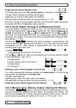
10.3.4 Output of Menu Functions

Each data menu, together with all displayed functions, can be output via inter-
face to a printer or computer (connection of peripheral devices, see manual
5.2). If you have selected the standard display, pressing the key 

 <PRINT>  

 leads

to a printout of the following listing:
Print data menu:


 <PRINT>  

Meas. point, meas. value, designation:

01:+0023.5 °C Temperature

MAXIMUM:    01:+0020.0 °C 

MINIMUM:    01:-0010.0 °C

PRINTTIMER:   00:01:23

Total memory capacity, free mem. in kB

MEMORY: S0512.1 F0324.4 A

The listing of the individual functions is given in section 6.6.1.

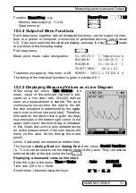
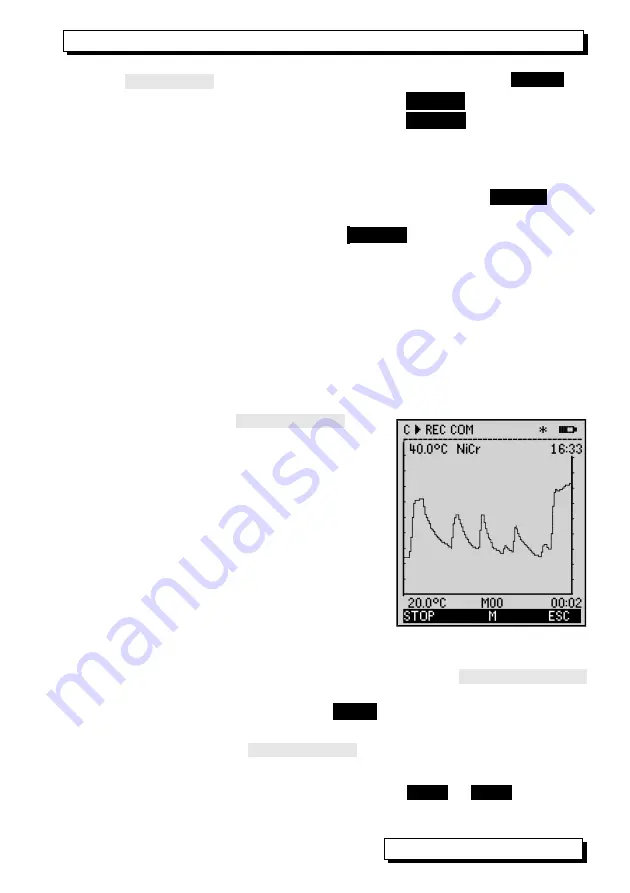
10.3.5 Displaying Measured Values as a Line Diagram 

When   using   the   menu  

  Line   diagram  

  the

meas.   value   of   the   selected   channel  is   indi-

cated   as   a   line   chart   with   100x200   dots   as

soon as a measurement is started. The curve

continuously moves from the right to the left,
the time resolution is determined by the 

cycle

,

each scan involves one point (dot). Therefore,

time data for the whole t axis is given as (days)

hours:minutes in the bottom right corner. In the

upper right corner the time of day is indicated.

In this mode, the curve is also updated during

an active measurement, if the user leaves the

menu (in this case, do not change the meas.

point!).
Limits, if activated, are entered as dotted lines.
The functions 

Analog Start

 and 

Analog End

 of the menu 

 Special functions 

(s. 11.4.4) can be used to set the display range of the y-axis. They can also be
entered directly at the axis using the key 

 PROG 

.

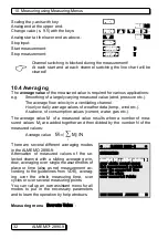
Displaying a measured value as line chart:

Enter the cycle in the menu 

 Times - Cycles 

.

Cycle:        00:00:05 

Time axis 120 x 5s = 10min:


 00:10

Select meas. channels using the keys:

  


or 


  


...

 ALMEMO

®

 2890-9

31  

Содержание ALMEMO 2890-9

Страница 1: ...____________________________ Operating Instructions Data Logger ALMEMO 2890 9 V3 5 11 09 2015 www ahlborn com ...

Страница 2: ...recharge 5 Socket DC 12volts Mains adapter ZB1112NA10 12Vvolts 2 A Charging adapter ZA 2690 LA 12V DC Cable isolat ZB 2590 UK 10 30V 6 LCD Status line C Cont measuring point scan ll Measurement Start Stop REC Memory record COM Output of meas values l l Meas start end programmed R01 Alarm relay status Light on pause Battery operation charge status 13 lines for functions Function of keys F1 F2 F3 F4...

Страница 3: ...ns Operation 16 7 3 External DC Voltage Supply 17 7 4 Sensor Supply 17 7 5 Switch On Off Reinitialisation 17 7 6 Data buffering 17 8 CONNECTION OF THE TRANSDUCERS 18 8 1 Transducers 18 8 2 Measuring inputs and Additional Channels 18 8 3 Isolation 19 9 DISPLAY AND KEYPAD 20 9 1 Display and Menu Selection 20 9 2 Function Keys 21 9 3 Control Symbols 21 9 4 Function Selection 22 9 5 Data Entry 22 10 M...

Страница 4: ...duration Timer 36 10 4 7 Averaging over the Cycle 36 10 4 8 Averaging over several Measuring Points 37 10 4 9 Volume Flow Measurement 38 10 5 Display of Several Measuring Points 39 10 5 1 Menu Multi Channel Display and Bar chart 39 10 5 2 Differential Measurement 40 10 5 3 Menu List of Measuring Points 40 10 6 Assistant Menus for Special Meas Operations 41 10 6 1 Thermal Coefficient 41 10 6 2 Wet ...

Страница 5: ...pply Voltage 62 11 4 3 Limit Value Responses 63 11 4 4 Analog Output Start and End 64 11 4 5 Output Function 64 11 4 6 Reference Channel 1 65 11 4 7 Reference Channel 2 or Multiplexer 65 11 4 8 Element Flags 65 11 5 Device Configuration 66 11 5 1 Device Designation 66 11 5 2 Device Address and Networking 66 11 5 3 Baud Rate Data Format 67 11 5 4 Language 67 11 5 5 Lighting and Contrast 67 11 5 6 A...

Страница 6: ...anual 3 1 Guarantee Every device has to pass through several quality tests before leaving the works For a perfect function a guarantee of two years from the delivery date is granted Before sending back the device please pay attention to the indica tions in chapter 12 Troubleshooting Should there actually be a defect please use the original packing material for depatch if possible and enclose an ex...

Страница 7: ...ame symbol Disposal of any such item as unsorted do mestic waste is strictly forbidden Please dispose of all packaging materials according to the applicable national waste management regulations Please dispose of cardboard boxes protective plastic packaging materials and all preservative substances separately and in the proper manner The disposal of the device itself also of device parts accessori...

Страница 8: ...njunction with unsuitable peripheral equipment Use of the device for any purpose other than that for which it is intended Damage caused by electrostatic discharge or light ning DANGER Risk of fatal injury caused by dangerously high voltage Such risks may occur in the following circumstances Use of the device with an unsuitable power supply and or in conjunction with unsuitable peripheral equip men...

Страница 9: ...ntegrated power supply are not electrically iso lated from one another 4 2 Handling batteries rechargeable batteries correctly When inserting batteries rechargeable batteries ensure that these are correctly polarized If the device will probably not be needed for a relatively long pe riod of time or if the batteries are empty remove the batteries this will prevent battery acid leaking onto the devi...

Страница 10: ...fiber optics Centronics manual section 5 2 The entire ALMEMO networking system manual section 5 3 All functions and their control via the interface manual section 6 A complete interface command list with all print outputs manual section 7 These operating instructions only cover features and controls that are specific for a certain device As a result many sections will often provide a note refer ri...

Страница 11: ...ngs Function Channels Maximum minimum average values and differences of certain measuring junctions can be programmed as function channels also in device internal channels and can be processed and printed like normal measuring junctions Furthermore function channels for special measuring tasks are provided to de termine the temperature coefficient Q DT and wet bulb globe temperature Dimension The ...

Страница 12: ... an analog output it may be an advantage to use semi continuous mode instead the output value will then always be refreshed at half the measuring rate set irrespective of the number of measuring points involved Measured Values The measured values of 1 to 20 measuring points can be indicated on the dis play in different menus that can also be configured in three font sizes as bar graph or as line c...

Страница 13: ...or an accurate recording of any measurement Start and end time date can be programmed in order to start or stop a measurement Cycle The Cycle is programmable between 1 s and 59 h 59 min and 59 s and pro vides a cyclic output of measured values to the interfaces or memories and also provides a cyclic averaging Print Cycle Factor If necessary the print cycle factor allows for limiting the data outpu...

Страница 14: ... specific style Nine keys four of them are soft keys can be used to operate the device This also allows you to fully program the sensors the device and the process control Output All data logs menu functions and stored measured values and programmed parameters can be provided as output to any peripheral equipment Various in terface cables can be used to provide a RS232 RS422 Centronics or Ethernet...

Страница 15: ...utput storage s 10 3 1 MANU or F2 Cyclic measurement Select Cycle Timer PROG Enter cycle hh mm ss s 9 5 Cycle Timer 00 05 00Sn Output format list columns n table t FORM or F3 Stop programming ESC or F4 Start stop the cyclic measurement s 10 3 2 START STOP or F1 Output of memory data to printer or computer Select the function Memory Free with PROG Memory data output s 11 2 6 PRINT or F3 Clear memor...

Страница 16: ...s adapter provided 12 volts 2 A ZB1112 NA10 delay may result in critically low discharge and damage the battery see 6 2 The NiMH rechargeable batteries can in fact be recharged at any time and in any charge status using the intelligent charge circuitry If the batteries are com pletely discharged the device will switch off but measured data and the time of day will be maintained in the battery buff...

Страница 17: ...be obtained using special connectors see Manual Sections 4 2 5 and 4 2 6 7 5 Switch On Off Reinitialisation To switch on or off use the slide switch 1 located on the left side of the de vice up ON down OFF The measuring menu most recently selected always appears first in the dis play After the device is switched off the real time clock continues to run and all saved values data and settings are re...

Страница 18: ...input sockets The additional channels can be especially used with humidity sensors with 4 measuring variables temperature humidity dew point mixture ratio or used for function channels If required the sensor can also be programmed with several ranges or scaling or depending on the pin assignment 2 or 3 sensors can be combined in one connector e g rH Ntc mV V mA V etc The additional measuring chann...

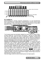
Страница 19: ...l power supply U or combined sensors within one connector The sensors must themselves be isolated or the device must be operated with an electrically isolated power supply mains adapter or connecting cable ZA2690 UK with DC DC converter For these sensors the electrical isolation must be disabled by means of switch S see above or by wire some inputs would otherwise be left without reference potenti...

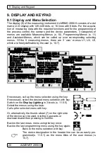
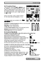
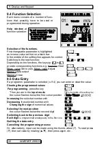
Страница 20: ...vice can be used rotating it upwards or downwards and then pressing to confirm Back to the last meas menu using the key once Back to the last programming menu using the key again Back to the menu selection with key ESC The device designation in the header line can be as easily pro grammed s 11 5 1 as the menu titles of the user menus s 10 7 20 ALMEMO 2890 9 ALMEMO 2890 9 MEASURING Menus Standard d...

Страница 21: ...arted ll or Measuring point scan started including storing REC Measuring point scan started incl output via interface COM Start end time of measurement is programmed l or l Relay status external output module off or on R or R01 Display illumination switched on or pause or Batt accumulator charge state 100 charged 50 charged discharged µµµµ µµµµµµµµ flashes Symbols for checking the measured value s...

Страница 22: ...r programming press the key PROG Then you are in the input mode P in the middle of the softkey line the cursor flashes below the first cursor position Cycle Timer 00 00 00 Increasing the selected number with Decreasing the selected number with Changing the sign of numerical values Selecting the next position the cursor flashes below the second digit Cycle Timer 00 00 00 Switching back to the previ...

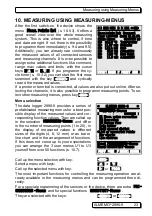
Страница 23: ...ection MEASURING Menus and differ in the number of measuring points 1 to 20 in the display of measured values in different sizes of the digits 4 8 12 mm or as bar or line chart and in the arrangement of functions If this does not come up to your expectations you can arrange the 3 user menus U1 to U3 yourself from over 50 functions s 10 7 Call up the menu selection with key ESC Select a menu with k...

Страница 24: ...ghest and lowest value including the time and date will each time be determined and stored from the acquired measured values of each measuring point The functions listed below are available to display these values function channels are available put them out s 11 3 10 The software AMR Control can be used to easily load or configure the menu Monitoring with Max Min times illustrated on the right as...

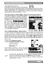
Страница 25: ...sured value at certain locations or at certain times in order to check the deviation from this reference value After selecting the function Meas Value s 9 4 in any menu a help window shows you all possi bilities of correction of the measured value The keys ZERO PROG can be used to store the displayed measured value as base value and as a result to set it to zero Function select Measuring Value 00 ...

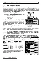
Страница 26: ...the case of dynamic pressure probes the zero point error is al ways written temporarily i e until you switch off to the calibration offset even if the channel is locked 10 2 3 Sensor Adjustment in the case of chemical sensors In the case of the following sensors with ADJ s 10 2 2 you get automati cally from the function measured value to the assistant menu Sensor adjust ment for a two point adjust...

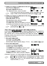
Страница 27: ...Correction a two point adjustment is also possible for other sensors Additionally to the zero point adjustment 10 2 2 the slope can be corrected with a second measuring point using the function Setpoint Pressing a button the correction factor is automatically determined and stored in the sensor connector 1 Zero point adjustment Set sensor to the zero state ice water unpressurized etc Set the meas ...

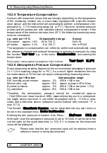
Страница 28: ...ring variables depend on the environmental atmospheric pressure s 11 3 9 measuring range list w PC As a result higher deviations from the normal pressure of 1013mbar can cause corresponding measuring errors e g error per 100 mbar Compensation range Rel humidity psychrometer approx 2 500 to 1500 mbar Mixture ratio cap approx 10 vapour pressure VP to 8 bar Dynamic pressure approx 5 800 to 1250 mbar ...

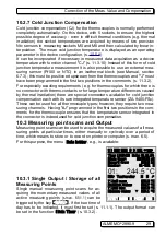
Страница 29: ...ed by thermal irradiation there are special connectors available for cold junction compensation each with its own integrated temperature sensor ZA 9400 FSx These can be used for all thermocouple types however they require two mea suring channels Having J programmed in the first two positions in the com ments for the thermocouple ensures that the temperature sensor integrated in the connector is in...

Страница 30: ...tion s 9 4 the cycle can be entered immediately s 9 5 After starting a measurement you can see the timer counting down to the next cycle Function Cycle Timer Cycle Timer 00 02 00 S Cycle hh mm ss Memory On Format List The key FORM can be used as the quickest way to set the required Output Format printouts s man 6 6 1 Change format FORM Format columns next to each other n Cycle Timer 00 02 00Sn Cha...

Страница 31: ... the meas value of the selected channel is indi cated as a line chart with 100x200 dots as soon as a measurement is started The curve continuously moves from the right to the left the time resolution is determined by the cycle each scan involves one point dot Therefore time data for the whole t axis is given as days hours minutes in the bottom right corner In the upper right corner the time of day...

Страница 32: ...ter gas etc The average value M of a measured value results when a number of mea sured values Mi are added together and then divided by the number N of the measured values Average value M i Mi N There are several different averaging modes in the ALMEMO 2890 9 Attenuation of measured values of the se lected channel with a sliding averaging win dow averaging over single measurements of place or time...

Страница 33: ...g over the number of the respective taken values within the range of 0 to 99 The smoothed measured value also applies for all subsequent evaluation functions Damping can thus also be used in conjunction with averaging over single measured values s 10 4 3 or at net measurements s 10 4 4 Meas value damping over e g 15 values with Damping 15 Continuous scanning should be switched off because otherwis...

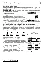
Страница 34: ...easured value s 10 5 5 10 4 3 Averaging over Manual Single Measurements Single manual meas point scans Ei are performed for an averaging of isolated measurements at certain points or times At all measuring points where mea sured values must be averaged the averaging must be switched on by using the averaging mode CONT 1 Stop measurement if it is started STOP 2 Set the averaging mode s 9 5 Averagin...

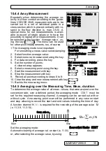
Страница 35: ... a measuring point using the key 01 m 7 Start the measurement with key START 01 11 22 m 8 Stop the measurement with key STOP 01 11 43 m 9 Record all points according to steps 6 to 8 10 Clear the array and new measurement with key CLEAR 11 Back to the measuring menu ESC 10 4 5 Averaging over the Measuring Time Meas duration To determine the average value of all meas values that were acqired over th...

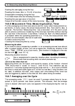
Страница 36: ...g duration If you want to stop a measuring operation or an averaging process see above after a certain length of time you can program the measuring duration in the menu Times Cycles or in a user menu this function is displayed in the sta tus bar with l see 10 1 4 Measuring duration function Measuring duration 00 00 00 Use a programmed measuring duration when recording to memory this ensures that r...

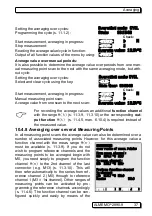
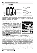
Страница 37: ...orresponding out put function M t s 11 4 5 man 6 10 4 is required instead of the measured value 10 4 8 Averaging over several Measuring Points In all measuring point scans the average value can also be determined over a number of associated measuring points However for this average value a function channel with the meas range M n must be available s 11 3 9 If you do not wish to program reference c...

Страница 38: ...average flow velocity v can be determined by a time based averaging s 10 4 5 a man 3 5 5 The rotating vane must be applied at one end the averaging has to be started and it is necessary to proceed uniformly over the whole cross sectional area and to stop the averaging when the other end of the cross sectional area is reached Alternatively the average flow velocity can also be determined by single ...

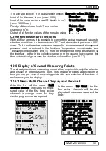
Страница 39: ...ces the standard volume flow see 11 3 2 10 5 Display of Several Measuring Points The already mentioned measuring menus allow on principle only the selection and display of one measuring point This chapter provides a description on how you can get several measuring points with your selection of functions si multaneously on the display 10 5 1 Menu Multi Channel Display and Bar chart After the first ...

Страница 40: ... it must be explicitly deleted s 11 3 9 If further differential channels are needed these can be created using the appro priated reference channels s 11 4 6 10 5 3 Menu List of Measuring Points The best overview of the meas system incl all meas values time of day date and cycle is obtained with the menu Meas point list From here it is also possible to get to the Sensor programming of all measuring...

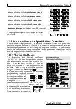
Страница 41: ...e performed quickly and easily there is a special assistant menu for each 10 6 1 Thermal Coefficient To determine the thermal coefficient q T1 T0 the two temperature sensors are connected as required see manual sec tion 3 2 to channels M0 and M1 and the heat flow plate to M2 The temperature dif ference T M1 T M0 is obtained automati cally on channel M9 with range Diff For this measuring operation ...

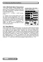
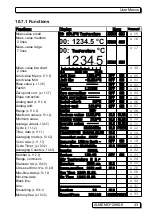
Страница 42: ...eas value and the combination of functions does not always match your applications in an optimum way Therefore you can freely configure the three user menus U1 to U3 in addition to the standard measuring menus using the software AMR Control You can use the following list of functions to individ ually place the functions you require in any sequence on your display up to the available space of 13 li...

Страница 43: ...alue s 10 1 2 Maximum value 1122 3 C CLR CLRA o 09 Minimum value Minimum value 19 3 C CLR CLRA o 10 Average value s 10 4 5 Average value CLR CLRA o 11 Cycle s 11 1 2 Cycle 00 00 00Un CLR FORM o 12 Time date s 11 1 1 Time 12 34 56 Date 01 02 00 CLR o 14 Averaging mode s 10 4 2 Averaging mode CONT CLR o 18 Conv rate s 11 1 3 Conv rate 10M s Cont OFF ON o 19 Cycle Timer s 10 3 2 Cycle timer 00 00 00U...

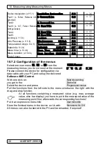
Страница 44: ...uration of the menus Select one user menu U1 U2 or U3 from the MEAS Menus measuring menus you do not need at the moment Please connect the device for configuration via data cable with your PC and call up the delivered Software AMR Control With one click on Network scanning you get to the Device list Select the device and press Program user menus Pull the functions from the left side to the menu wi...

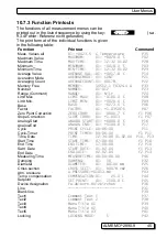
Страница 45: ...ASE 01 0273 0 C P06 Factor FACTOR 01 1 0350E 1 P07 Zero Point Correction ZERO CORR 01 0000 7 C f1 P06 Slope Correction SLOPE CORR 01 1 0013 f1 P07 Analog Start ANALOG START 01 0000 0 C P16 Analog End ANALOG END 01 0100 0 C P17 Cycle PRINT CYCLE 00 06 00 P11 Cycle Timer PRINT TIMER 00 06 00 f1 P11 Time Date TIME 12 34 00 01 02 04 P10 P13 Start Time START TIME 07 00 00 f1 P10 End Time END TIME 17 00...

Страница 46: ...he specified format in the first line on the left side and the date on the right side s 9 5 Function Time and Date Time 12 34 56 Date 01 05 00 Format of time and date hh mm ss dd mm yy 11 1 2 Cycle with Storage Activation and Output Format The Cycle is used for cyclic storage and outputs of measuring data on the in terface it corresponds to the print cycle of other ALMEMO devices the mea suring cy...

Страница 47: ...cycle Cycle 00 15 00 Sn 11 1 3 Conversion Rate Continuous Measuring Point Scan If required for measuring point scans the conversion rate can in function Conv rate be increased from 2 5 up to 10 50 or 100M sec s man 6 5 There is also an option SA0000 Q4 for setting the measuring rate to 400 mops but this is only possible for 1 measuring channel at a time Half continuous measuring point scan The pos...

Страница 48: ...er the connection lines wherever possible use twisted wires At 100 or 400mops saving to memory is only possible with the mul timedia card but not with the internal EEPROM 11 1 4 Start date and time of day end date and time of day measuring duration A sequence of measurements can at certain points in time be automatically started and stopped For this purpose the start time and date and the end time...

Страница 49: ...me in the function File name s 10 3 1 If the external memory is connected at the start of any measuring operation it will be used In the course of the measuring operation it must not be un plugged this would cause temporarily buffered measured values to be lost External memory capacity available External memory 64 00 MB Memory capacity still free Memory free 21 75 MB File name maximum 8 characters...

Страница 50: ... must be readout and cleared before the next recording Menu Recording to memory Internally available memory capacity Memory internal 512 0 kB Available free memory space Memory free 217 5 kB External memory capacity available External memory 64 01 MB Linear memory without overwriting of data Ring memory Activate ring memory with overwriting of data ON Ø Nb of act channels to calculate the storing ...

Страница 51: ...assistant menu START STOP The operation via interface is described in the manual section 6 6 The function of start time and end time or measuring duration is described here in sec tion 11 1 4 the limit value responses in sec tion 11 4 3 and the varieties of relais and trigger in section 11 6 2 11 2 5 Scanning mode For autonomous operation and or for scan ning by computer there are 4 scanning modes...

Страница 52: ...a logger being operated on a cyclic basis is to be monitored occasionally by computer Internal cyclic scanning is not influenced in any way by software scanning in Win Control safe initialization must be switched off The internal cycle is started as and when the software starts it may also have been started previously Scanning via the internal cycle does not cause any data to be output to the inte...

Страница 53: ...lect number with keys FIRST NEXT LAST To select a time interval Enter the start time using the format hh mm ss Start time 07 00 00 Enter the end time using the format hh mm ss End time 17 00 00 Enter the start date using the format dd mm yy Start date 01 05 00 Enter the end date using the format dd mm yy End date 01 05 00 Perform complete output of data memory ALL Output of a numbered measurement ...

Страница 54: ...ode allows the rest appears in grey Output of the sensor programming of all ac tive measuring points command P15 s man 6 2 3 with key PRINT 11 3 1 Selecting the Input Channel To query or to program the parameters of a sensor it is first necessary to se lect the menu SENSOR PROGRAMMING and then to set the required input chan nel by using the key or For this only connected sensors and activated chan...

Страница 55: ... to apply to just one thermocouple s 10 2 7 11 3 3 Averaging Mode The types of averaging which are defined through the function Averageing mode are described in section 10 4 2 Function no averaging Averaging mode Averaging over all running measuring point scans CONT Averaging over all scans in one cycle CYCL 11 3 4 Locking the Programming of the Sensor The function parameters of each measuring poi...

Страница 56: ...most cases necessary to set a zero point shift and to per form a multiplication with a certain factor The functions BASE and FACTOR are available for this A detailed description of the scaling including an exam ple can be found in the manual section 6 3 11 Indicated value Corrected Measured Value BASE x FACTOR The FACTOR can be programmed in the range from 2 0000 to 2 0000 For factors over 2 0 or ...

Страница 57: ...e Celsius will be converted into degrees Fahrenheit The cold junction compensation can be switched off by using the characters C The following dimensions are automatically generated entering 2 corre sponding characters m at ms at mh at Wm g at g 11 3 9 Selecting the Measuring Range If users want to program the connectors on their own or if they frequently change the measuring range it must be cons...

Страница 58: ... ZA 9000 FS 270 0 60 0 C AuFe W5Re W26Re C ZA 9000 SSC 0 0 2320 0 C WR26 Ntc Type N ZA 9000 FS 30 00 125 00 C Ntc Ntc Typ N ZA 9040 SS3 0 000 45 000 C Ntc3 Ptc Typ Kty84 ZA 9040 SS4 0 0 200 0 C KTY Millivolt 1 ZA 9000 FS 26 000 26 000 mV mV 1 Millivolt ZA 9000 FS 10 000 55 000 mV mV Millivolt 2 ZA 9000 FS 260 00 260 00 mV mV 2 Volt ZA 9000 FS 2 6000 2 6000 V Volt Difference Millivolt 1 ZA 9000 FS ...

Страница 59: ...CO2 Sensor FY A600 CO2 0 0 2 500 CO2 O2 Saturation with TC a PC FY A640 O2 0 260 O2 S O2 Concentration with TC FY A640 O2 0 40 0 mg l O2 C Function channels s 11 3 10 Mixture ratio wth PC FH A646 0 0 500 0 g kg H AH Dew point temperature FH A646 25 0 100 0 C H DT Partial vapour pressure FH A646 0 0 1050 0 mbar H VP Enthalpy with PC FH A646 0 0 400 0 kJ kg H En Rel humidity psychr with PC FN A846 0...

Страница 60: ...ring ranges and units see above under the sub heading Function channels there is a group for representing function pa rameters in measured value processing or calculated results from linking cer tain measured values on measuring channels see Manual 6 3 4 Reference to the actual measuring channels is provided by one or two reference chan nels For all function channels the default reference channels...

Страница 61: ...antly performed 1 Provision of special measuring ranges with internal characteristic s 10 3 9 2 Linearization of signals for voltage current resistance or frequency set by the user 3 Multi point calibration of all sensors The ALMEMO 2890 9 can as standard evaluate all appropriately programmed connectors With the special KL variant it is also possible to convert measur ing signals into appropriate ...

Страница 62: ...put The data recording also allows to sup press unnecessary measured values and as a result saves memory space Enter the print cycle factor s 9 5 in function Print cycle factor 01 Clearing the print cycle factor with the key CLR 11 4 2 Minimum Sensor Supply Voltage Similarly to all ALMEMO devices the sensor supply voltage is also monitored in the 2890 9 It is also displayed in the menu Power suppl...

Страница 63: ...es 4 relays 0 to 3 This mode also has to be set as variant 2 in the output module s 11 6 2 man 6 10 9 Output socket A2 Setting the relay module to variant 2 EA Trigger Alarm relay int allocated 2 Rx int allocated Activating relay x at limit value exceeding Max 7 Action max Rx Activating relay y at limit value undershooting Min 7 Action min Ry Clearing the relay allocation using the key CLR Startin...

Страница 64: ...ll pa rameters of an analog output 11 4 5 Output Function If not the real measured value to the measuring point Mxx but only the Max Min Average or Alarm value is required then this function can be programmed as output function see manual 6 10 4 As a result only the corresponding function value will be considered for storing and analog or digital output For control of the changed output function t...

Страница 65: ...ence channel 1 In all other cases it is possible to change the pin assignment in the connector by changing the input multiplexer with the function Multiplexer s manual 6 10 2 Programming of the ref channel 2 absolute 1 RefChannel 2 00 Programming of the ref channel 2 relative 1 RefChannel 2 01 Measuring inputs B and A GND referred 1 Multiplexer B A Measuring inputs C and A GND referred 1 Multiplex...

Страница 66: ...rally acquire the measured values of several instruments that are located at different places see manual 5 3 For communicating with networked devices it is mandatory that all devices have the same baud rate and an own individual address as only one device is allowed to respond to each command Therefore before any network operation it is necessary that all connected devices are set to different dev...

Страница 67: ... 11 5 5 Lighting and Contrast The background lighting of the display can be switched on or off in 3 levels in the selection menus by using the key ON or in the function Lighting of the device configuration attention the power consumption is fife times higher in level 3 If the lighting is switched on when a mains supply adapter is not connected the lighting will switch off in a configurable lightin...

Страница 68: ...t Modules The data logger ALMEMO 2890 9 has two output sockets A1 and A2 to allow an output of the measured values as analog or digital values or as alarm signals Furthermore it is possible to trigger various functions through trigger pulses To suit all possibilities while keeping the hardware requirements at a mini mum all necessary interfaces have been in tegrated into the ALMEMO output con nect...

Страница 69: ...ne function variant see Manual 6 6 4 the new V6 relay trigger analog adapter ZA 8006 RTA3 offers up to 10 relays or op tions with 2 of these as trigger inputs or up to 4 as analog outputs All elements can be config ured individually for these functional variants Old output cables can be reconfigured for V6 functions by means of AMR Control These modules can be connected equally well to out put soc...

Страница 70: ...ariant 8 Driven externally permits manual activation of the relays via the keypad or via the interface see Manual 6 10 10 Relay variant 8 8 Driven externally For manual activation of relays press ON or OFF The watchdog setting for the RTA then appears see above Trigger inputs For the purpose of controlling the measuring sequence 2 trigger inputs are provided at ports 8 and 9 keypad or optocoupler ...

Страница 71: ...e measured value for the selected measuring channel Mxx is output in variant 0 In this mode the semi continuous measuring rate see 11 1 3 is the most suitable because in this way the analog output will be processed most frequently Assigning an analog output to a measuring point In variant 2 Assigned internally after selecting the Mxx function you can program the measuring point to be output 2 Assi...

Страница 72: ...ge will always be 12V Mains adapter 12 0 V The max admissible current is also displayed Maximum current 1 0 A If the accumulators are discerned contact there appears in the display Accumulators Ø The accumulator capacity must be programmed Capacity 1600mAh With mains adapter ZB1112 NA10 the process of charging the batteries to 1600 mAh takes 2 5 hours and for higher capacities accordingly longer F...

Страница 73: ...1 Fct Locking the functions and keys 0 none 1 data input switching on and off PROG ON OFF ZERO ADJ 2 clearing measured data CMEM CLR CLRA 3 start stop output measuring operation START STOP MANU ARRAY PRINT 4 function selection measuring point selection PROG F M No password locking with new password Password Locked with password enter correct password Password Select locking level menu and function...

Страница 74: ...k cabling for inadmissible electrical connection disconnect all suspicious sensors connect hand held sensors and operate them in air or connect dum mies short circuit AB at thermocouples 100 W at Pt100 sensors and check then reconnect sensors successively and check If an error occurs with one sensor check the wiring isolate the sen sor if necessary prevent influences from disturbances by shielding...

Страница 75: ...rt report and possibly control printouts Additionally the software AMR Control allows to print the monitor pages including the program ming and also to save an extensive function test in the device list or the termi nal operation and to print it out 13 DECLARATION OF CONFORMITY Ahlborn Mess und Regelungstechnik GmbH declares herewith that measuring instrument ALMEMO 2590 carries the CE label and c...

Страница 76: ...wheel Memory 512kB EEPROM approx up to 100000 Meas values Time and Date real time clock buffered with Lithium battery Microprocessor M16C62P Power supply ext 9 13V DC Rechargeable battery pack 6 NiMH cells AA 1 6 Ah 5A fuse Mains adapter ZB1112 NA10 230 VAC to 12 VDC 2 A Adapter cable electr isolated ZB 2590 UK 10 30 VDC to 12 VDC 1 A Current consumption without active mode approx 37 mA Input and ...

Страница 77: ...ement OA 2690 KL Accessories Memory connector including SD card minimum 128 MB RS ZA1904 SD Spare rechargeable battery pack NiMH 7 2 volts 1600 mAh ZB 2590 AP Mains adapter with ALMEMO connector 12 volts 2 A ZB 1112 NA10 DC Adapter cable 10 to 30V DC 12V 0 25A electr isolated ZA 2590 UK ALMEMO Recording cable 1 25 to 2 00 V ZA 1601 RK ALMEMO Data cable V24 Interface electr isolated max 115 2kB ZA ...

Страница 78: ...aging over the Cycle 10 4 7 36 Averaging over the Measuring Time 10 4 5 35 Bar chart 10 5 1 39 Base 11 3 6 56 Baud Rate 11 5 3 67 Changing the Dimension 11 3 8 57 Charge mode 11 7 72 CJ Temperature 11 5 8 68 Clear memory 11 2 6 54 Cold Junction Compensation 10 2 7 29 Cold junction temperature 11 5 8 68 Comment 11 3 2 55 Compensation 10 2 25 Configuration 11 5 8 68 Configuration of the menus 10 7 2...

Страница 79: ... Supply 7 3 17 Factor 11 3 6 56 Function Channels 11 3 10 60 Function Keys 9 2 21 Function Printouts 10 7 3 45 Function Range of the ALMEMO 2890 8 5 1 10 Function Selection 9 4 22 Guarantee 3 1 6 Housing 14 1 76 Hysteresis 11 5 7 56 68 Initial Operation 6 15 Introduction 5 10 Inverted relay control 11 6 2 70 Isolation 8 3 19 Keypad 9 20 Language 11 5 4 67 Level of damping 10 4 1 33 Lighting 11 5 5...

Страница 80: ...meter 11 5 8 68 Operation conditions 14 1 76 Order No 14 2 77 output cables 11 6 2 69 Output Format 11 1 2 30 46 Output Function 11 4 5 64 Output Modules 11 6 68 Output of Menu Functions 10 3 4 31 Peak Value Memory 10 1 2 24 Power supply 14 1 16 76 Print Cycle Factor 11 4 1 62 Process flow control 5 1 3 13 Product overview 14 2 77 Programmed analog value output 11 6 3 72 Programming Menus 11 20 46...

Страница 81: ... 10 6 41 Standard display 10 1 24 Starting and Stopping of measurements 11 2 4 51 Storage Activation 11 1 2 46 Switch On Off 7 5 17 Technical Data 14 1 76 Temperature Compensation 10 2 5 28 Thermal Coefficient 10 6 1 41 Time and Date 11 1 1 46 Time and Date of Maximum Value 10 1 2 24 Transducers 8 1 18 Trigger inputs 11 6 2 70 Troubleshooting 12 74 Two point Adjustment 10 2 4 27 U Sensor Min 11 4 ...

Страница 82: ...14 Appendix 14 4 Your contact 82 ALMEMO 2890 9 ...

Страница 83: ...Your contact We take every possible care but the risk of inaccuracy can never be altogether excluded We reserve the right to make technical changes without advance notice ALMEMO 2890 9 83 ...

Страница 84: ...14 Appendix 84 ALMEMO 2890 9 ...

Отзывы: