Mini Merlin Installation, Operation & Maintenance
Rev: 03 05-22
7
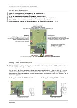
Circuit Board Overview
Damage to PCBs when creating cable entry points may void any warranty!
Take care when making connections to high voltage connectors!
Any damage attempting to remove the circuit board may void any warranty!
All Class 2 wiring is to be installed within flexible tubing to maintain segregation between circuits!
Wiring of different circuits shall be separated by means of routing, clamping or barrier!
For field connections other than connected Heat detectors use wires suitable for at least 167°F (75°C)
Wiring
–
Gas Solenoid Valve
When the installation includes a standing pilot, ensure the internal auto reset dip switch is in the OFF position requiring a
manual reset of the fuel supply!
A gas solenoid valve should be powered using the terminals marked [VALVE OUT]. When the valve out terminal is
wired to a normally closed (NC) gas solenoid valve, the device can be used to isolate the gas supply for multiple
appliances. Use an external transformer (not supplied) to close a 24VAC gas solenoid valve that could supply gas to
one or more appliances.
Gas Supply Controlled by 100-120VAC Solenoid Valve Gas Supply Controlled by 24VAC Solenoid Valve


