


6
FIGURE 9
FIGURE 10
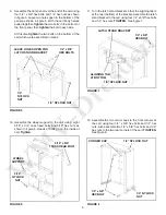
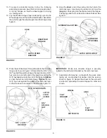
13. To prevent accidental tipping during the following
assembly procedures, lower the cart to rest upside down
on its top fl anges, so that the wheel support is facing
up. See fi gure 9.
14. Lay the drawbar tongue (open side facing up) onto the
Wheel Support and the Latch Stand Bracket. Assemble
the axle through the wheel support and the tongue. See
fi gure 9.
15. Place the latch lock lever through the slot in the draw bar
tongue as shown in fi gure 10. Assemble the 5/16" x 3-
3/4" hex bolt through the tongue, the lever and two 5/16"
hex nuts (one on each side of the lever). Assemble the
5/16" hex
lock
nut onto the end of the bolt and
lock
tighten
so that the bolt can still rotate freely.
Tighten
the two
5/16" hex nuts against the sides of the latch lock lever
so that the lever is centered in the slot. See fi gure 10.
FIGURE 11
FIGURE 12
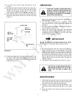
IMPORTANT:
Make sure drawbar tongue is securely
locked to the latch stand bracket by the latch lock lever.
17. Assemble a fl at washer, a wheel with the valve stem
facing out, and another fl at washer onto the axle as
shown in fi gure 12. Secure the wheel on the axle with
a cotter pin, spreading the ends. Repeat on other end
of axle.
16. Hook the
short
end of the spring into the hole in the
latch lock lever. Use the spring puller tool to hook the
long
end of the spring into the square hole in the tongue.
The spring puller tool can be stored when fi nished. See
fi gure 11.
AXLE
DRAW BAR
TONGUE
LATCH STAND
BRACKET
5/16" NYLOCK NUTS
5/16"
NYLOCK
NUT
LATCH
LOCK
LEVER
5/16" x 3-3/4"
HEX BOLT
COTTER PIN
WHEEL
FLAT
WASHER
FLAT
WASHER
AXLE
LONG END
OF SPRING
LATCH LOCK LEVER
SPRING PULLER TOOL
Содержание 45-01003
Страница 10: ...10 NOTES...


