


2
Installation
Internal components of the XFe Analyzer
18
Seahorse XFe Analyzer Operating Manual
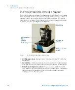
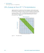
Internal components of the XFe Analyzer
Removing the side doors reveals the measurement chamber in which the assay
is conducted. The electro-optics hardware is enclosed in a card cage in the rear
chamber, and this is connected to the probe head through a set of fiber optic
cable bundles. The base of the enclosure contains the primary controller board
and heater assembly. (See
.)
•
LCD Message screen
- Displays current instrument action and Thermal tray
temperature.
•
Cover latches
- Pull on indented hand-holds molded into the side doors (not
shown) to lift them up, exposing the internal components of the instrument.
•
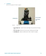
Probe head and injection manifold
- The probe head consists of 24 or 96
“light pipes” to carry the optical signals to and from the sensors. The Injection
manifold uses compressed air to inject compounds loaded into Sensor
cartridge ports into the assay wells.
Figure 1.
XFe Front/Side view. Base color may vary.
LCD Message
screen
Cover latches (not
shown)
Fiber bundles
Thermal tray
Probe head and
Injection
manifold
Содержание Seahorse XFe
Страница 1: ...Seahorse XFe Analyzer Operating Manual...
Страница 4: ...4 Seahorse XFe Analyzer Operating Manual...
Страница 12: ...1 Introduction Technical Specifications 12 Seahorse XFe Analyzer Operating Manual...
Страница 22: ...2 Installation Setup and interconnects cable installation 22 Seahorse XFe Analyzer Operating Manual...
Страница 38: ...4 Maintenance Additional Resources 38 Seahorse XFe Analyzer Operating Manual...
Страница 39: ......
Страница 40: ...www agilent com Agilent Technologies Inc 2018 Second Edition June 2018 S7804 90001 S7804 90001_REV A...


