Agilent Technologies G4560A Скачать руководство пользователя страница 19

Agilent G4560A Upgrade Kit

Installation Guide

19

2

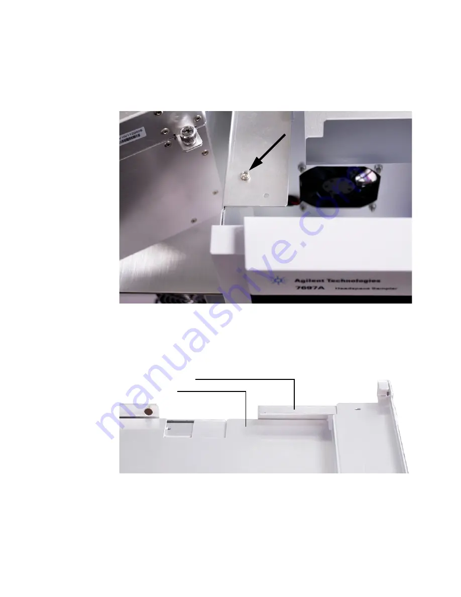
Remove the T- 20 Torx screw from the headspace chassis bracket found 
to the right of the oven assembly and behind the display panel 
(

Figure 22

). This screw will be reused in 

step 5

.

3

Place the top instrument cover onto the headspace. 

Be sure that the top instrument cover sits below the headspace 
chassis bracket as shown in 

Figure 23

.

Figure 22

Remove the T-20 Torx screw from the headspace chassis bracket

Figure 23

Top instrument cover installed correctly

Headspace chassis bracket

Top instrument cover

Содержание G4560A

Страница 1: ...111 Vial Model Oven Assembly 1 Table 2 Box 2 labeled G4556 67005 Description Quantity 111 Vial Model Cover Kit includes 1 T 20 Torx screws 5 pk 1 Front cover 1 Top instrument cover with 3 cables pre i...

Страница 2: ...2 Installation Guide Agilent G4560A Upgrade Kit Parts Identification Figure 1 111 Vial Model Oven Assembly...

Страница 3: ...Installation Guide 3 Figure 2 111 Vial Cover Kit T 20 Torx screws Front cover Top instrument cover 0515 0433 G4556 81020 G4556 00217 Panel tray power cable G4556 60142 BCR power to panel cable G4556 6...

Страница 4: ...4 Installation Guide Agilent G4560A Upgrade Kit Figure 3 G4556 64014 111 Vial Model Tray kit 7697A Tray Assembly Shipping clamp Shipping clamp removal instructions Vial racks...

Страница 5: ...rts Supplied and Parts Identification for information Prepare the GC and 7697A 12 Vial headspace sampler 1 Set your GC oven GC inlet headspace oven and transfer line to ambient temperatures and wait f...

Страница 6: ...rs from the headspace sampler Remove the covers shown in Figure 4 from the headspace sampler Figure 4 Covers to remove from the 12 vial model headspace sampler Front cover Top cover tray Top cover Rig...

Страница 7: ...Remove two T 20 Torx screws on the back of the headspace sampler b Lift and remove the top cover tray and remove the T 20 Torx screw under the top cover tray c Remove the top cover 3 Remove the front...

Страница 8: ...ures the cover in place Figure 6 b Slide out then lift to remove the pneumatics front cover Remove the oven assembly Figure 6 T 20 Torx screw securing the pneumatics front cover CAUTION Do not remove...

Страница 9: ...loosen the T 20 Torx captive thumbscrew in the back area of the pneumatics assembly Figure 8 c Lift the pneumatics assembly straight up rotate the unit about 90 degrees counterclockwise and lay it ac...

Страница 10: ...Figure 9 The oven heater connection jack is located on the left side behind the oven compartment facing the front of the headspace sampler b Disconnect the ribbon cable from P1 on the control board T...

Страница 11: ...he four T 20 Torx screws shown in Figure 11 4 If any broken glass exists carefully remove it from the carousel and vial tray area using a vacuum cleaner 5 Carefully lift the oven assembly out of the h...

Страница 12: ...the headspace sampler The oven side racks are located just below the oven compartment on either side of the headspace chassis as shown in Figure 12 1 Remove the T 20 Torx screw on the side oven racks...

Страница 13: ...60A Upgrade Kit Installation Guide 13 Figure 13 Removing the T 20 Torx screw on the left side oven rack Figure 14 Removing the T 20 Torx screw on the right side oven rack Left side oven rack Right sid...

Страница 14: ...top row of support rivets Be sure all eight rivets fit into each of the holes in the left side rack Figure 16 5 Pull the left side rack towards the front of the headspace sampler until it slides into...

Страница 15: ...ift the oven assembly and slide it backwards until the rivets on the side racks align with the holes in the oven assembly base 3 Install four T 20 Torx screws at the corners of the oven assembly base...

Страница 16: ...bon cable to connection P1 on the control board Figure 18 5 Route the oven sensor cable through the insulated opening in the headspace chassis as shown in Figure 19 Figure 18 Connect the ribbon cable...

Страница 17: ...ugh the opening in the headspace chassis and to the main board as shown in Figure 20 Be sure that the cables run cleanly from the oven assembly to the main board This will ensure enough cable slack to...

Страница 18: ...matics assembly up rotate the unit about 90 degrees clockwise and lower it into position on the top left of the headspace sampler b Tighten the two T 20 Torx captive thumbscrews in the front of the pn...

Страница 19: ...panel Figure 22 This screw will be reused in step 5 3 Place the top instrument cover onto the headspace Be sure that the top instrument cover sits below the headspace chassis bracket as shown in Figu...

Страница 20: ...ure 24 passes entirely through the opening on the top instrument cover 4 Route and connect the tray cables to connections P41 P42 and P43 on the main board Figure 25 Figure 24 Top instrument cover cor...

Страница 21: ...ade Kit Installation Guide 21 5 Install the T 20 Torx screws shown in Figure 26 to secure the top instrument cover to the headspace Figure 26 Install T 20 Torx screws to secure the top instrument cove...

Страница 22: ...all 111 vial model tray 1 Lower the back of the tray assembly onto the top instrument cover while holding the front of the tray assembly above the headspace 2 Slide the cables into the tray cable clip...

Страница 23: ...nections Figure 28 4 Lower the front of the tray assembly onto the headspace Be sure it is sitting level on the headspace sampler 5 Remove the tray shipping clamp Refer to the instruction sheet provid...

Страница 24: ...down and to the right until the cover is in position on the headspace sampler b Install the two T 20 Torx screws on the left side to secure the cover to the headspace sampler 3 Install the pneumatics...

Страница 25: ...re by using the Agilent Instrument Utilities software version B 01 05 SP1 or later 1 Load Agilent Instrument Utilities 2 Navigate to Configuration Licenses and enter your FSE license information 3 Sel...

Страница 26: ...firmware from http www chem agilent com b Unzip the firmware file s c In the Firmware Update utility click Add Browse to and select the files unzipped in the previous step The new firmware version wi...

Страница 27: ...formation checkbox Figure 31 7 In the HCV App row select the same firmware revision as is installed for the LCV App Figure 32 Figure 31 Showing detailed version information in the Firmware Update util...

Страница 28: ...idental or consequential damages in connection with the furnishing use or performance of this document or of any information contained herein Should Agilent and the user have a separate written agreem...

Отзывы: