Agilent Technologies G3375A Скачать руководство пользователя страница 9

Installing a Single-Channel Analog Input Board on a 6850 GC

9

b.

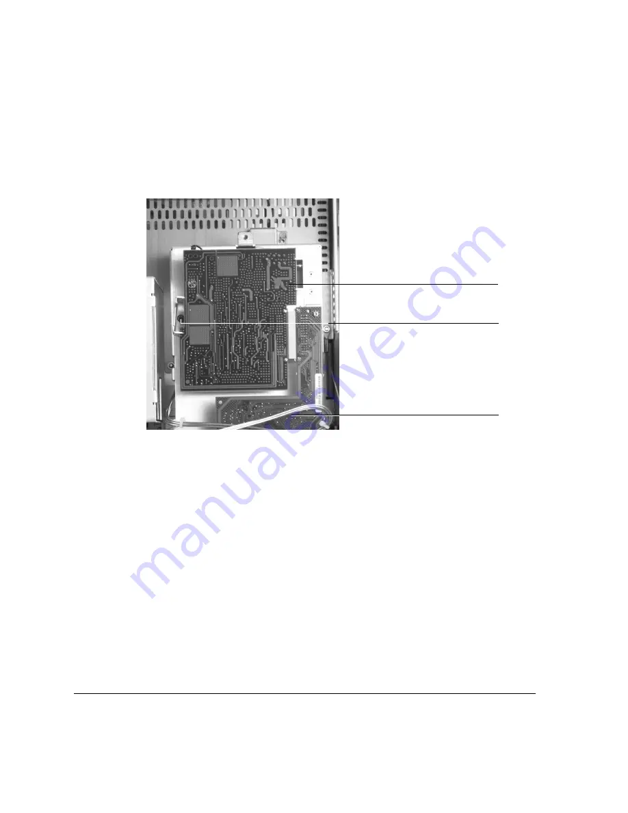
For large boards, such as the FPD board shown below, remove the 
detector PCB bracket holding the detector board in place. 

Detector board

Detector PCB bracket

A/D converter board

     (FPD shown)


mounting screw

Содержание G3375A

Страница 1: ...iption Quantity Part number Grommet 1 0400 0914 Screw M3 0 5 12 mm long pan head 1 0515 1084 Torx screw M4 18 mm long 2 0515 3034 Screw M4 0 7 12 mm long 2 0515 2496 Analog signal cable general purpose 6 pins 1 G1530 60560 Analog input board 1 G1556 60015 Detector PCB bracket 1 G2397 00020 Insulation detector blank 1 G1530 00660 MS detector plate 1 G2630 20980 Installing a Single Channel Agilent 6...

Страница 2: ...iew Caution Before starting review the safety information listed at the end of this document 1 Prepare the GC 2 Remove the lid top cover 3 Remove the existing detector and flow manifold 4 Raise the lid to the service position 5 Remove existing detector PC board 6 Position the analog cable 7 Install the AIB 8 Install the insulation detector blank and detector plate 9 Connect the analog signal cable...

Страница 3: ...od or set all GC temperatures to ambient 35 C 2 Allow time for all heated zones to cool 3 Turn off the GC and unplug the power cord 4 If you have an injector installed set it aside Remove the lid top cover Remove T 20 Torx screws 8 places Remove detector cover if desired Remove vent tubing if present ...

Страница 4: ...nifold the other manifolds are similar but vary in the number of gas connections 3 Trace the ribbon cable from the flow manifold and disconnect it from the harness 4 Remove the three manifold mounting screws 5 Remove the screws holding the detector assembly in place You will need a new top cover FID flame ionization detector Remove four mounting screws Flow manifold µECD shown Gas fittings Cover p...

Страница 5: ...mounting screws µECD micro cell electron capture detector Remove four mounting screws FPD flame photometric detector Remove four mounting screws You will need a new top cover 6 Lift the detector and flow manifold out of the lid as a unit Mounting screws Mounting screws Two mounting Two mounting screws screws ...

Страница 6: ...in the hole under the detector Raise the lid to the service position 1 Open the lid Locate the counterbalance cam in the left rear corner under the lid Loosen the screw on the right side of the cam This allows the stop plate to drop down 2 Raise the lid until it is stopped by the safety cable 3 Raise the stop plate and tighten the screw to lock the lid in the upright service position WARNING The l...

Страница 7: ...he two bottom screws on the detector electronics cover Caution Board components can be damaged by static electricity use a properly grounded static control wrist strap before gaining access to the detector electronics area and when handling the boards and any of the cables connecting to the boards 2 Remove the top screw on the cover 3 Lift and remove the detector electronics cover Remove screw Det...

Страница 8: ...the detector board for removal a For small boards such as the µECD shown below remove the M3 screw that secures the detector board to the printed circuit board PCB bracket M3 screw securing board to bracket Detector PCB bracket Detector board µECD shown A D converter board ...

Страница 9: ...log Input Board on a 6850 GC 9 b For large boards such as the FPD board shown below remove the detector PCB bracket holding the detector board in place Detector board Detector PCB bracket A D converter board FPD shown mounting screw ...

Страница 10: ...nnect and remove all cables from the old detector board All detectors Disconnect the ribbon cable The ribbon cable connector will not pass through the rubber grommet in the hole Use a small screwdriver to push the grommet to the top of the lid the cables will now fit through the hole Reinstall the grommet in the lid for later use after you have removed the ribbon cable A D converter board detector...

Страница 11: ...f the lid The FID PC board is shown below TCD Unplug the two wire switching valve cable at the connector To release the PRT and filament wires press down on the orange tabs Pass the disconnected wires through the hole to the top side of the lid Ribbon cable connector Ignitor cable connector Switching valve PRT wires Filament wires cable connector ...

Страница 12: ...12 Installing a Single Channel Analog Input Board on a 6850 GC 7 If you have a TCD or FPD detector PCB bracket installed remove the existing detector PCB bracket Bracket for TCD or FPD removed ...

Страница 13: ...talled underneath the lid thru the top of the lid Pass the analog cable through the opening at the back of the lid See the figure below Caution Take caution when routing the spade lug ends of the analog cable through the openings in the lid of the GC To avoid possible damage to the cable make sure to pass the spade lug ends through each opening before pulling the rest of the cable through Cable ro...

Страница 14: ...ctor PCB bracket using the two 12 mm long M4 screws Position the PCB bracket according to the figure below 2 Remove the AIB from its static control bag 3 Make certain switches 1 and 2 are in the ON position See the figure below 4 Plug the AIB into the A D converter board and secure it to the detector PCB bracket using the M3 screw Bracket positioned properly Switches 0 and 3 are in OFF position sw...

Страница 15: ...ble may be shipped with the black ferrite core positioned right at the end of the cable secured there with a tie wrap If necessary remove the tie wrap and adjust the ferrite core position to allow the bending of the AIB cable as shown in the figure above Analog cable connected M3 T 20 screw AIB Detector PCB bracket A D Converter board ...

Страница 16: ... detectors Without a detector installed the lid will open too quickly posing a hazard to the user and potential damage to the GC To compensate for the counterbalanced lid and to protect exposed wiring install the detector plate and insulation blank as described below 1 Install the circular insulation blank in place of the detector that you just removed See the figure below Insulation blank ...

Страница 17: ...Installing a Single Channel Analog Input Board on a 6850 GC 17 2 Use two 18 mm long M4 screws to install the detector plate over the insulation blank as shown in the figure below Detector plate Screws ...

Страница 18: ...r electronics cover and tighten all three screws 2 Lower the stop plate on the lid cam Pull the lid forward until the cam follower rests on the curved surface of the cam Raise the stop plate behind the cam follower and tighten the screw 3 Close the lid Be sure that the folded gas lines do not interfere with it 4 Install the lid top cover 5 Restore power Connector 1 Signal name Connector 2 Quick Di...

Страница 19: ...Installing a Single Channel Analog Input Board on a 6850 GC 19 ...

Страница 20: ...ards of design and the intended use of the instrument Agilent Technologies assumes no liability for the customer s failure to comply with these requirements Acknowledgements Torx is a trademark of Textron Inc In the manual A warning calls attention to a condition or possible situation that could cause injury to the user A caution calls attention to a condition or possible situation that could dama...

Отзывы: