33
Installing the Autosampler
Sample Trays
Supported trays for the different Autosampler
Half-Tray Combinations
Half-trays can be installed in any combination enabling both 2 ml-and
6 ml-vials to be used simultaneously.
Numbering of Vial Positions
The standard 100-vial tray has vial positions 1 to 100. However, when
using two half-trays, the numbering convention is slightly different. The
vial positions of the right-hand half tray begin at position 101 as follows:
Left-hand 40-position tray: 1 - 40
Left-hand 15-position tray: 1–15
Right-hand 40-position tray: 101–140
Right-hand 15-position tray: 101–115
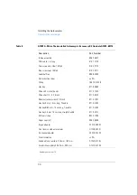
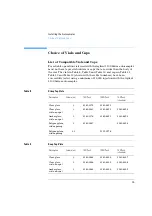
Table 6
Supported trays for the Autosampler (G1313A)
'HVFULSWLRQ
3DUW1XPEHU
Tray for 100 x 2 ml vials
G1313-44500
Halftray for 15 x 6 ml vials
G1313-44503
Halftray for 40 x 2 ml vials
G1313-44502
Table 7
Supported tray for the Autosampler (G1329A
/
G1389A / G2260A)
'HVFULSWLRQ
3DUW1XPEHU
Thermostattable Tray for 100 x 2 ml vials
G1329-60001
Halftray for 15 x 6 ml vials (for G2260A only
*
)
G1313-44503
*
This tray is not recommended when using a thermostat
Содержание G1313A
Страница 1: ...s1 Agilent 1100 Series Standard Micro and Preparative Autosamplers Reference Manual ...
Страница 3: ...Reference Manual Agilent 1100 Series Standard Micro and Preparative Autosamplers ...
Страница 12: ...12 Contents ...
Страница 39: ...2 2 Optimizing Performance How to optimize the autosamplers to achieve best results ...
Страница 49: ...3 3 Troubleshooting and Test Functions The modules built in troubleshooting and test functions ...
Страница 93: ...93 Troubleshooting and Test Functions Step Commands ...
Страница 159: ...5 5 Parts and Materials Detailed illustrations and lists for identification of parts and materials ...
Страница 160: ...160 Parts and Materials Main Assemblies Main Assemblies Figure 19 Autosampler Main Assemblies 5 3 4 2 1 9 8 7 6 ...
Страница 166: ...166 Parts and Materials Analytical Head Assembly Figure 21 Analytical Head Assembly 2 3 4 5 6 1 ...
Страница 191: ...191 Parts and Materials Remote Cables NOTE START and STOP are connected via diodes to pin 3 of the 3394 connector ...
Страница 216: ...216 Introduction to the Autosampler Electrical Connections ...
Страница 217: ...7 7 Theory of Operation Theory of operation of mechanical hardware electronics and instrument interfaces ...
Страница 244: ...244 Theory of Operation The Main Power Supply Assembly ...
Страница 265: ...265 Introduction to the Control Module Diagnostics and Tests ...
Страница 268: ...268 Introduction to the Control Module Diagnostics and Tests ...
Страница 269: ...9 9 Specifications Performance specifications of the Agilent 1100 Series Standard Micro and Preparative Autosamplers ...
Страница 274: ...274 Specifications Performance Specifications ...
Страница 275: ...10 Legal Safety and Warranty Information ...
Страница 286: ...286 Agilent Technologies on Internet ...
Страница 290: ...290 Index ...
Страница 291: ......


