Service Guide E8364-90001
4- 27
PNA Series Microwave Network Analyzers
Troubleshooting
E8362A, E8363A, E8364A
Measurement System Troubleshooting
Measurement System Troubleshooting
This section provides troubleshooting procedures for the measurement portion of the PNA
series network analyzer. In this section, the analyzer is used as a tool to help isolate the
suspected faulty functional group. Once the faulty functional group is determined,
troubleshooting steps are provided to help you isolate the faulty assembly or part.
Before you begin—consider: Where do you see a problem?
If you are seeing a problem at
Preset
, perform the standard S-parameter test set
troubleshooting procedure, starting with:
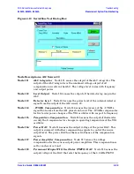
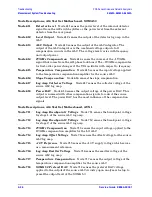
“Verifying the A, B, R1, and R2 Traces” on
You should also consider the problem indications which are observed and whether the
observed condition is a
soft
failure or a
hard
failure. With a
soft
failure, the network
analyzer's performance has degraded to an unacceptable level, yet it continues to operate
and displays no error messages. For this type of failure, performance tests must be
conducted to isolate the problem. Begin with viewing the error terms as described in
This will help isolate most problems. If additional tests are required, refer to
“Performance Tests (Agilent N2721A Software Package)” on page 3-30
With a
hard
failure, the PNA does not perform well and displays one or more error
messages. To diagnose and repair a hard failure: Refer to
below and
perform the procedures in those sections that are applicable for your particular error
message.
Error Messages
PHASE LOCK LOST
: The level of the signal from at least one of the reference receivers, and
sensed by the phase lock board, is too low to be accurately captured. This could be due to a
problem in the source group, signal separation group, or receiver group (refer to
the Source Group” on page 4-32
“Checking the Signal Separation Group” on page 4-46
and
“Checking the Receiver Group” on page 4-50
SOURCE UNLEVELED
: The source ALC circuits on the A12 source or the A16 test set
motherboard—E8363A and E8364A only—is running open-loop. For the E8362A, replacing
the A12 source assembly can correct this. For the E8363A or E8364A, check the cable
connections for W37 and W38 from the A23 and A24 detectors to the A16 test set
motherboard, and for W39 from A16 to the A21 SOMA 50. If the problem is associated with
one port and not the other, replace the detector associated with the problem port. If the
problem affects both ports, replace the A16 test set motherboard.
Содержание E8362A
Страница 11: ...Service Guide E8364 90001 1 1 1 Safety and Regulatory Information ...
Страница 19: ...Service Guide E8364 90001 2 1 2 General Product Information ...
Страница 29: ...Service Guide E8364 90001 3 1 3 Tests and Adjustments ...
Страница 79: ...Service Guide E8364 90001 4 1 4 Troubleshooting ...
Страница 139: ...Service Guide E8364 90001 5 1 5 Theory of Operation ...
Страница 169: ...Service Guide E8364 90001 6 1 6 Replaceable Parts ...
Страница 215: ...Service Guide E8364 90001 7 1 7 Repair and Replacement Procedures ...
Страница 287: ...Service Guide E8364 90001 A 1 A Error Terms ...
Страница 302: ...A 16 Service Guide E8364 90001 Error Terms PNA Series Microwave Network Analyzers Error Term Data E8362A E8363A E8364A ...
Страница 303: ...Service Guide E8364 90001 B 1 B Option Enable Utility ...
Страница 309: ...Service Guide E8364 90001 C 1 C Firmware Upgrades ...
Страница 313: ...Service Guide E8364 90001 D 1 D Operating System Recovery ...


