


7
E5072A Network Analyzer Confi guration and block diagram
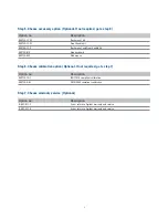
E5072A Network Analyzer Upgrades
The following upgrade kits are available for adding the options of the E5072A
E5072A Block Diagram
R1
A
R2
B
Port 1
Port 2
RCVR R1
IN
SOURCE OUT
CPLR T
HRU
SOURCE
OUT
RCVR A
IN
CPLR A
R
M
RCVR B
IN
CPLR A
R
M
CPLR T
H
RU
SOURCE OUT
RCVR R2
IN
SOURCE OUT
Source
SPDT Switch
Solid -state
Attenuator
(65 dB)
Mechanical
Step Attenuator
(60 dB,
10 dB step)
Bias-Tee
Bias-Tee
Mechanical
Step Attenuator
(60 dB,
10 dB step)
REF 1
REF 2
Figure1. Simplifi ed test set block diagram
Option no
Description
E5072AU-008
Add frequency offset mode (Customer installable)
E5072AU-010
Add time domain analysis (Customer installable)
E5072AU-1E5
Add high stability time base (Return to Agilent)
E5072AU-027
Upgrade to removable HDD
1
(Return to Agilent)
E5072AU-028
Removable hard disk kit. (Spare hard disk,Customer installable)
E5072AU-285
Maximum frequency upgrade from 4.5 GHz to 8.5 GHz for E5072A-245
(Return to Agilent)
1. New hard disk is not included in this option and an original disk is reused. Order E5072AU-028 if spare disk is necessary


