


42
Chapter 3
Quick Start Guide
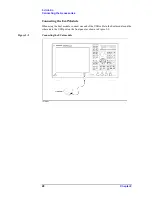
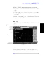
Names and Descriptions of E5070/E5071A parts
2. Data Entry Bar
Using the data entry bar, you can enter numeric data or label names.
3. Channel Title Bar
Using the channel title bar, you can cause a title arbitrarily entered by the user to appear on
each channel.
4. Softkey Menu
A group of softkeys used for specifying the setup of the E5070/E5071A.
5. Trace Bar
Displays the settings for each trace (from left: trace number, S-parameter, data format, and
scale). Using the mouse, you can also select the active trace.
6. Marker Indicator
Indicates a marker position on the horizontal axis.
7. Marker Value
Displays the stimulus value and response value of each marker. Symbol > displayed to the
left of a marker number indicates that that marker is the active marker. When the reference
marker is set ON, symbol
D
is displayed instead of the marker number and indicates the
marker value of the reference marker. When the reference marker is set ON, the stimulus
value and response value of other markers indicate the differences from the values of the
reference marker.
8. Reference Line Indicator
Displays the position of the reference line.
9. Marker
Used for reading out values on a trace. Using a marker makes it easy to analyze
measurement results or change stimulus settings. The active marker is represented with an
inverted triangle.
10. Channel Status Bar
Displays channel-specific information on the E5070/E5071A for each channel. This
information consists of the channel number, the start frequency (center frequency), the stop
frequency (span frequency), ON/OFF of the error correction function, and whether or not
the sweep is in progress. When the averaging function is ON, the channel status bar also
displays that information.
11. Instrument Status Bar
Displays the information on the status of the E5070/E5071A that is common to all
channels.
Содержание E5070A ENA Series
Страница 12: ...12 Chapter1 Introduction of This Manual Overview of the E5070A E5071A ...
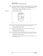
Страница 17: ...Chapter 2 17 Installation Checking the Shipment 2 Installation Figure 2 1 E5070A E5071A Accessories ...
Страница 30: ...30 Chapter2 Installation Power Supply and Blown Fuses Figure 2 10 Power cable options ...
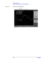
Страница 56: ...56 Chapter3 Quick Start Guide Measurement Example of a Bandpass Filter ...
Страница 61: ...Index 61 Index U USB port front panel 41 User s Guide 6 V VBA Programmer s Guide 6 ...
Страница 62: ......


