


Chapter 7
7-3
Service
Theory of Operation
Theory of Operation
The probe uses a Gallium Arsenide FET integrated circuit amplifier which provides unity gain. This
amplifier microcircuit re6 V and
4 Vdc to operate. These voltages are provided by the regulator
assembly.
The regulator assembly converts the +15 volt and
12.6 volt supplies from the host instrument with two
voltage regulators. The regulator supplies the +6 and
4 voltages to the amplifier microcircuit.
The most common failures in the probe will all result in loss of signal through the probe, and will show
up if the operator’s check is performed. The most common failures are expected to be:
1. Destruction of the amplifier microcircuit due to static electricity (proper anti-static precautions not
taken).
2. Probe power tip damage (caused by the operator dropping the probe with the sleeve retracted).
3. Possible regulator failure.
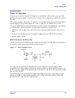
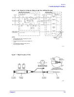
ESD Protection at the Probe Tip
The FET integrated circuit amplifier is located at the tip of the probe. The FET input of the amplifier is
protected by a bidirectional voltage limiter as shown in
.
Figure 7-1
Probe Tip Input Circuit
The voltage limiter element has a negligible effect on circuit operation for input voltages within
specification. The voltage limiter is a non-linear element: it begins to conduct current at about 2.5 volts.
It effectively limits voltages at the amplifier input to less than
4 volts. This prevents amplifier damage
from low levels of ESD.
Even with the protection provided by the voltage limiter element, the probe is still sensitive to ESD.
High levels of ESD can cause permanent damage to the voltage limiter element itself. Careful ESD
precautions must be observed when using the probe.
Содержание 85024A
Страница 4: ...iv ...
Страница 7: ...1 1 1 General Information ...
Страница 13: ...2 1 2 Accessories ...
Страница 19: ...3 1 3 Installation ...
Страница 24: ...3 6 Chapter3 Installation Returning the Product for Service ...
Страница 25: ...4 1 4 Operation ...
Страница 30: ...4 6 Chapter4 Operation Operator s Check ...
Страница 31: ...5 1 5 Performance Tests ...
Страница 40: ...5 10 Chapter5 Performance Tests Average Noise Level ...
Страница 41: ...6 1 6 Replaceable Parts ...
Страница 46: ...6 6 Chapter6 Replaceable Parts Parts Lists ...
Страница 47: ...7 1 7 Service ...
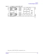
Страница 60: ...7 14 Chapter7 Service Replacement Procedure Figure 7 11 Regulator Parts and Wiring ...
Страница 64: ...7 18 Chapter7 Service Connector Inspection and Cleaning ...


