


Operation
6
To Install the Battery
Before using the probe for the first time, you must install the
battery. When the probe is turned on, the green battery indication
LED should light up. If not, replace the battery.
1
Disconnect the probe from the circuit and the oscilloscope.
WARNING
Do not replace the battery while probe is in use.
2
Set the probe’s switch to the
OFF
position.
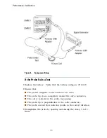
3
Unscrew the battery compartment screw (shown on
Figure 1 on
page 5
) and pull out the battery compartment cover.
4
Install the new 9V battery and put the cover back on.
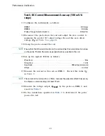
To Perform a Current Measurement
1
Read the warnings in
“Safety”
on page 8.
2
Connect the current probe to an input channel on the oscilloscope.
WARNING
Connect the probe to the oscilloscope or voltage measuring instrument before
clamping the probe around a conductor.
3
Set the current probe to its least sensitive range (10 mV/A).
4
Select the 0.5 V/division range on the oscilloscope.
5
Clamp the probe on the conductor to be measured and read the
current flowing directly on your oscilloscope.
You may also use your oscilloscope to amplify the signal while
using the 100 mV/A probe range (which offers the best accuracy
and least phase shift).
WARNING
It is possible to change the range on the current probe without removing the
probe from the current carrying conductor, but never exceed the permissible
peak ratings of 1000 mV peak or 2000 mV peak-to-peak maximum. The peak
ratings by range are: 10A peak on the 100 mV/A range, 100A peak on the
10 mV/A range.