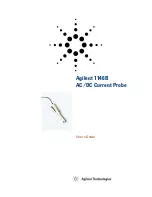
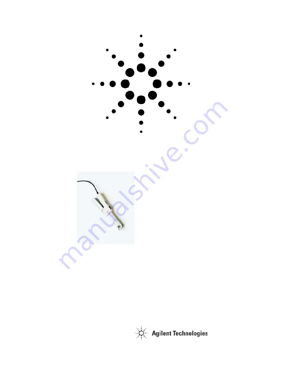
Agilent 1146B
AC/DC Current Probe
User’s Guide
Страница 1: ...Agilent 1146B AC DC Current Probe User s Guide...
Страница 2: ...s or implied with regard to this manual and any information contained herein including but not limited to the implied warranties of merchantability and fitness for a particular purpose Agilent shall n...
Страница 3: ...afety Standards 12 Typical Response Curves 13 Performance Verification 15 If the Probe Fails a Test 16 Test 1 DC Current Measurement Accuracy 10 mV A range 17 Test 2 AC Current Measurement Accuracy 10...
Страница 4: ...ital oscilloscope or other voltage measuring instrument which has the following features BNC input connector Range capable of displaying 0 2V to 0 5V per division Minimum input impedance of 1 M Before...
Страница 5: ...uminates during measurement this indicates that the peak value exceeds the instrument response level and that the output is distorted Use the range selection switch to change the probe to a higher ran...
Страница 6: ...an input channel on the oscilloscope WARNING Connect the probe to the oscilloscope or voltage measuring instrument before clamping the probe around a conductor 3 Set the current probe to its least sen...
Страница 7: ...due WARNING Make sure that the probe is completely dry before reconnecting it to a power source Product Markings This symbol indicates the Environmental Protection Use Period EPUP for the product s to...
Страница 8: ...be around a conductor WARNING Never use the probe on circuits rated higher than 600 Vac RMS CAT II or 300 Vac RMS CAT III or with float voltage greater than 600 V WARNING Never leave the probe clamped...
Страница 9: ...on WARNING If you energize the instrument by an auto transformer for voltage reduction or mains isolation the ground pin of the input connector terminal must be connected to the earth terminal of the...
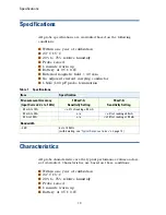
Страница 10: ...stics are the typical performance values and are not warranted Characteristics are based on these conditions Within one year of calibration 23 C 5 C 20 to 75 relative humitidy Probe zeroed 1 minute wa...
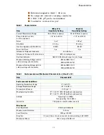
Страница 11: ...mum Working Voltage refer to safety warnings and standards 600Vac RMS CAT II 300Vac RMS CAT III Maximum Floating Voltage refer to safety warnings and standards 600Vac RMS CAT II 300Vac RMS CAT III Tab...
Страница 12: ...68 2 6 frequency range 10 Hz to 55 Hz amplitude 0 15 mm Handle Lexan 920A UL 94 V2 Dimensions 231 mm x 36 mm x 67 mm Weight 330 g 11 6 oz with battery Color Light gray Output cable Insulated coaxial c...
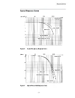
Страница 13: ...Characteristics 13 Typical Response Curves Figure 2 Typical Frequency Response Curve Figure 3 Typical Phase Shift Response Curve...
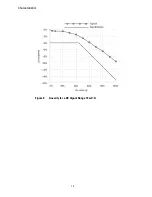
Страница 14: ...Characteristics 14 Accuracy Figure 4 Linearity for a DC Signal Range 10 mV A...
Страница 15: ...ure 5 10 Turn Coil Table 5 Required Equipment for Performance Verification Tests Description Critical Specifications Recommended Model Part Numbers Digital Multimeter 2 required AC DC voltage and curr...
Страница 16: ...that The probe s magnetic contact surfaces are clean The probe tip closes completely around the coil s conductors The coil is centered in the probe tip opening The probe tip is perpendicular to the c...
Страница 17: ...irection in the coil matches the current direction arrow on the probe Position the probe as perpendicular as possible to the coil 4 Set up the Agilent 33120A as follows Waveform Sine Frequency 1 kHz A...
Страница 18: ...sary to achieve a current of at least 10 mA 11 Measure the voltage output by the probe VPROBE on DMM 2 and record in Table 7 12 Do the calculations specified in Table 7 to determine if the probe passe...
Страница 19: ...be passes the test Table 7 AC Current Measurement Accuracy Record 10 mV A range Measurement Recorded Value Current in Coil IC Probe Output Voltage VPROBE Calculate Maximum Probe Output Voltage As VPRO...
Страница 20: ...t direction in the coil matches the current direction arrow on the probe Position the probe as perpendicular as possible to the coil 20 Set up the Agilent 33120A as follows Waveform Sine Frequency 1 k...
Страница 21: ...amplitude if necessary to achieve a current of at least 10 mA 27 Measure the voltage output VPROBE by the probe on DMM 2 and record in Table 10 28 Do the calculations specified in Table 10 to determin...
Страница 22: ...he probe passes the test Table 10 AC Current Measurement Accuracy Record 100 mV A range Measurement Recorded Value Current in Coil IC Probe Output Voltage VPROBE Calculate Maximum Probe Output Voltage...
Страница 23: ...I indicator lights 5 K knob 5 L Linearity for a DC signal Range 14 O OL 5 Operating 11 operating temperature range 11 P Peak Overload OL Indicator 5 peak ratings 5 probe cleaning 7 R range selection s...
Страница 24: ...01146 92005 Agilent Technologies Manual Part Number 01146 92005 Printed in Malaysia...