


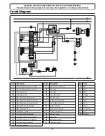


A
Burner head
Burner base
Brass venturi
ArtNo.272-0025 - 90 Aga Professional - Control panel removal
WARNING – SERVICING TO BE CARRIED OUT ONLY BY AN AUTHORISED PERSON
Disconnect from electricity and gas before servicing. Check appliance is safe when you have finished.
4
When servicing or replacing gas carrying components
disconnect from gas before commencing operation and
check appliance is gas sound after completion. When
checking for gas leaks use a liquid leak detector at all joints
and connections to check for leaks in the system. Use a
product specifically manufactured for leak detection. Leak
testing of the appliance shall be conducted in accordance to
the manufacturer’s instructions.
DO NOT use a flame to check for gas leaks.
DO NOT use reconditioned or unauthorised gas
controls.
Disconnect from electricity supply before
commencing servicing, particularly before removing
any of the following: control panel, side panels,
cooktop tray, or any of the electrical components
or cover boxes. Before electrical reconnection make
sure the range is electrically safe.
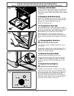
1. Remove Control Panel
Disconnect from electricity supply
Pull off the control knobs.
Open the oven door and remove the 3 fixing screws
underneath the control panel (
Fig.1
).
Remove 3 screws from the upper rear of the control panel.
Pull the control panel forward and support so that the wires
are not strained.
To gain access behind the control panel it is also necessary to
remove the cooktop (see
‘2. Remove the Cooktop’
).
Reassemble in reverse order. When replacing leads refer to
the wiring diagram. Check operation of timer, ignition, and
oven light switches.
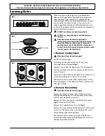
2. Remove the Cooktop
Disconnect from electricity supply
Remove the grates and burner heads. If there are screws
holding the cooktop burners to the cooktop, remove them
(not the spark electrode fixing screws).
Remove the 22mm brass venturi and lift the burner base
(
Fig.2
). Disconnect the HT leads.
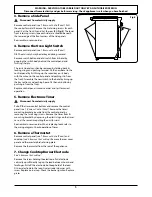
Remove the 3 cooktop fixing screws (A) (
Fig.3
).
Remove the screws holding the flue grille stays and if the rear
extension is fitted remove the screws holding that as well.
Lift the cooktop clear of the appliance.
Reassemble in reverse order ensuring that the leads are
reconnected. When replacing the cooktop take care not to
damage the ignition electrodes.
Servicing Notes
Fig.1
Fig.2
Fig.3
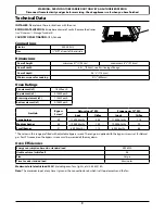
Содержание Professional 90
Страница 1: ...Professional 90 Dual Fuel F200094 01 Service Instructions...
Страница 2: ...ii...
Страница 10: ...10...
Страница 11: ...11...


