


2.2 CONNECTION TO A GAS SUPPLY
The gas supply piping and connection to the
appliance must be installed in accordance with the
various regulations listed on the front page of this
document.
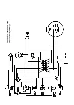
2.3 CONNECTION TO AN ELECTRICAL SUPPLY
The electrical connections must comply with the
relevant standards listed on the front page of this
document.
2.4 CONNECTION TO A WATER SUPPLY
Not applicable to these appliances.
2.5 PRE-COMMISSIONING CHECK
Ensure that all open-top burners (where applicable)
and oven linings are properly located, and that oven
grid-shelves slide in and out easily. Check that all
packing material has been removed.
It is necessary for the gas pressure to be checked
before the unit is commissioned, and a suitable
pressure gauge must be connected to the pressure
test point(s) as follows:
Open Top Burners (where applicable).
Pull off the gas tap knobs, and remove the control
panel, thus revealing the test-point.
Ovens
FIRST ENSURE ELECTRICITY SUPPLY IS OFF
Remove the three Pozidriv screws securing the black
control panel, and draw the panel forward on its
slides. Remove the burner grille (4 Pozidriv screws).
Connect a pressure gauge to the outlet test point
immediately below the multifunctional gas control.
Note that inlet and outlet points are provided on the
control also.
The gas pressure to the open-top burners is adjusted
by means of the external governor mounted at the
rear of the appliance, whilst the oven pressure is
controlled by adjusting the appropriate screw on the
gas control-valve.
When adjusting the pressure on a range (i.e. G1102)
it is recommended that the oven, and two of the open
top burners be lit during the operation.
2.5.2 Adjusting The Oven Burner Pressure
Proceed as follows:
a) If possible, purge the supply lines of air. On G1102
ranges, this is simply effected by opening one or
two of the open top burner taps and applying a light
to the burner. On oven units, it may be necessary
to slacken off a joint in the incoming supply pipe,
taking care to re-tighten.
b) Light the oven, as described in the accompanying
User's Instructions. At this stage, take care not to
touch live connections which are now exposed
behind the withdrawn oven control panel.
c) Check all connections for gas-soundness, using
soap and water solution.
d) With the pressure gauge connected to the outlet
pressure test point adjust the pressure, which
should be 15 mbar (6 in w.g.), by turning the screw
in the regulator screw on the gas control. This is
situated under the white plastic cover, which must
be pulled off. To increase the pressure, turn the
screw clockwise, and vice-versa.
e) Adjust the open-top burner pressure by turning the
screw in the governor turret. Replace the protective
cap afterwards.
f) Switch off the appliance by depressing the OFF
button on the gas control valve, and turn off the
electricity supply at the mains. Replace test point
screws, control panels etc.
2.5.3 Checking The Performance Of
The Controls
Oven
a) Light the oven as detailed in the User's
Instructions, set the thermostat at 250
o
C and
allow the oven to heat up, ensuring that the fan is
operating and turning anti-clockwise when viewed
from the front.
b) Turn the thermostat down to its lowest setting, and
check that the oven burner goes out, but leaving
the pilot burner lit.
c) Turn the thermostat knob to a high setting,
whereupon the oven burner should re-light
smoothly and with little or no delay.
d) Check that the fan stops, and the oven burner goes
out, when the oven doors are opened.
e) Check the operation of the power switch. When
OFF the fan should stop, and the main burner be
extinguished. The pilot burner, however, remains
lit.
f) Check to timer. This does not turn off the gas to the
oven, but simply provides the user with an audible
sign that a pre-set time has elapsed.
g) Depress the oven light button and check hat the
light is operational.
Open Top
Light the open top as detailed in the User's Instruc-
tions. Check that the ignition is smoooth and without
delay. Repeat this operation several times.
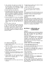
2.5.4 Multifunctional Control
Access to the control is gained upon withdrawal of the
control panel. See section 3.2.1.
The control is an SIT Electrosit 0.810.156 and
contains a number of features for effecting
adjustments. Refer to Figure 4.


