Page 18
16/05/2019
R05.0
4.4
Setting the air gap
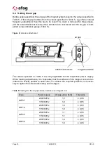
During series assembly, the air gap of the magnet system is set to the values specified in
Table 5. If this air gap deviates from the values specified in Table 5, e.g. after a natural
frequency adjustment, then this has to be reset. The cover is removed for this purpose,
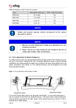
and the side attachment screws of the armature are unscrewed and the air gap is read-
justed using a distance gauge (Table 9).
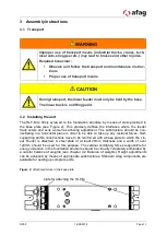
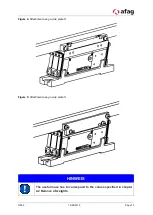
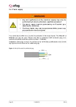
Figure 8:
Armature attachment
The values specified in Table 5 are only applicable for the respective power supply.
When making adjustments, it is imperative that the surfaces of the magnet core and ar-
mature are exactly parallel to each other. To achieve the required precision, it is neces-
sary to tighten the screws alternately and in stages.
Table
5:
Settings for the air gap between armature and magnet core
Type
Power supply
Air gap value [mm]
Tolerance
HLF07
230V/50Hz
1,0
± 0,05
115V/60Hz
1,0
± 0,05
HLF12
230V/50Hz
1,0
± 0,05
115V/60Hz
1,0
± 0,05
HLF25
230V/50Hz
1,1
± 0,05
115V/60Hz
1,1
± 0,05
HLF50
230V/50Hz
1,0
± 0,05
115V/60Hz
1,0
± 0,05
attachment screws
air gap
magnet armature

