background image


Standard Sign System 

Maintenance Manual 


Publication Number ASMM2010 • Version 1.0 • April 2011 

Содержание KC640

Страница 1: ...Standard Sign System Maintenance Manual Publication Number ASMM2010 Version 1 0 April 2011...

Страница 2: ...y energy and if not installed and used in accordance with this and related manuals may cause interference to radio communications Operation of this equipment in a residential area may cause harmful in...

Страница 3: ...Firmware and Manual Versions and Revisions 13 Change Management 13 Aesys Terminology and Terms 14 Chapter 2 System Overview 15 Introduction to the Standard Sign System 15 Chapter 3 KC640 CCU Operatio...

Страница 4: ...et Disable 29 Emergency Button Error 29 Emergency Panic Alarm Feature 30 Manual Input Messages MIM 31 Manual Input Message MIM Procedure 31 Special MIM Feature Key Functions 31 CCU Technical Informati...

Страница 5: ...rview 52 Electrical Cable Harness Information Overview 52 Sign Mounting Brackets Identification 52 Printed Circuit Boards 52 Destination Sign Parts Catalog Listings 53 List of Figures Figure 1 Manual...

Страница 6: ...ing Displays Screen 27 Figure 29 Dash Sign Enabled and Disabled Feature Main Screen 28 Figure 30 Protocol Decimal Hexadecimal Setup Feature Main Screen 28 Figure 31 Access Code Password Option Initial...

Страница 7: ...l Connection Diagram Detail B 62 Figure 59 General Connection Diagram Detail C 63 Figure 60 General Connection Diagram Detail D 64 Figure 61 General Connection Diagram Detail E 65 Figure 62 General Co...

Страница 8: ...age Page Duration Values and Durations 26 Table F Sign CPU Circuit Board DIP Switch Settings for Address Settings 41 Table G Hardware related Troubleshooting 49 Table H KC640 CCU Troubleshooting 50 Ta...

Страница 9: ...ion Disclaimer IMPORTANT This manual contains information about the Standard Sign System manufactured by Aesys Inc No representations or warranties are made as to the accuracy or completeness of the i...

Страница 10: ...ish Version Revision Description Revised Date Revised By Approved By 1 0 Initial release based on Aesys Publication Number ASMM2009 Version 4 1 04 01 2011 CW SD CM Cautionary Symbols Table B describes...

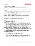
Страница 11: ...the cable from the positive terminal before performing any installation or service procedure Only trained service personnel should perform the procedures outlined in this maintenance manual These proc...

Страница 12: ...using the voltage is short circuited to ground causing protection hazards We recommend that the user contact Aesys personnel if any anomalies with the display sign occur Aesys cannot be responsible in...

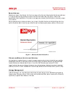
Страница 13: ...e 1 Manual Version Information Firmware and Manual Versions and Revisions It is important to note that there is no direct correlation between the versions of both firmware and the maintenance manual F...

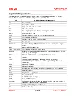
Страница 14: ...tch packaged in a single group EMI Electro Magnetic Interference ENT OR Enter The Enter Key on the CCU control panel EPROM Erasable Programmable Read Only Memory A non volatile read only memory erasab...

Страница 15: ...Diagram The system is usually composed of the following components in each installation per bus KC640 Central Control Unit with microprocessor This is the central element that manages all system compo...

Страница 16: ...agnostic information The operator can use the CCU s LCD to verify that the destination message or code number selected with the keyboard is the one he wishes to display before sending the command to a...

Страница 17: ...ch to second level CCU set up F2 Mode selection internal message Disabled F3 Press to set route line code Disabled F4 Press to set a public relation P R message F5 Press to set destination A F6 Press...

Страница 18: ...econds see Figure 7 NOTE Your boot program code version may vary depending upon the latest version that has been updated and or purchase date of your system BOOT xxxxxx WAITING Figure 5 Start Up and B...

Страница 19: ...lot connector Once the SMC is installed all the way into the slot the CCU will beep three times indicating the card is present and the LCD will display the following messages CARD PRESENT READING CARD...

Страница 20: ...the message list from the first message destination entered then counts down and F7 This key starts the message list from last message destination entered then counts up Figure 9 KC640 Central Control...

Страница 21: ...form the following steps 1 Verify which sign has the Status 2 error If using a USP4 type sign the problem may be internal so contact Aesys technical support for further assistance 2 Check to ensure th...

Страница 22: ...UST be J1708 compatible in order to use this option and the dash sign must be enabled To enter dash sign information perform the following steps 1 Press F3 the Route key and the LCD will display Machi...

Страница 23: ...ssage Select Between Two Destinations DEST A and DEST B Referring to Figure 16 and Figure 17 the DEST A F5 and DEST B F6 key functions are commonly used when a vehicle is traveling to and from the sam...

Страница 24: ...n Referring to Figure 18 and Figure 19 to blank the signs turn off all LEDs press the CL key until the LCD shows DISABLE DISPLAYS ENT to confirm When the ENT key is pressed the message DISABLED DISPLA...

Страница 25: ...are 16 possible brightness levels To manually change the automatic brightness to another value perform the following steps 1 Press F1 and the second level access code screen will appear see Figure 20...

Страница 26: ...4 indicates that the sign is disabled since the selected value is 0 zero If the value was 1 the sign would be enabled NOTE Referring to Figure 24 in the first line of the display INTERN DISP 0 the 0 z...

Страница 27: ...inus mode will let the user enter the line and or route number and destination message independently Since Aesys does not recommend users to perform this operation specific steps are not included in t...

Страница 28: ...Sign Enabled and Disabled Feature Main Screen Protocol Decimal Hexadecimal Setup Feature F7 IMPORTANT Before using this feature contact technical support for assistance This feature is used when rece...

Страница 29: ...ve the capability of reloading your destination messages be sure you have a backup SmartMedia card with the latest destinations available To reset the default values on the CCU perform the following s...

Страница 30: ...L POLICE 911 or some other approved message When the vehicle s exterior facing signs display the alert message the display message on the sign controller mounted inside the vehicle will only display P...

Страница 31: ...original destination or message press the code number that corresponds to that destination and then press the ENT key Special MIM Feature Key Functions The F1 key is used to delete one character at a...

Страница 32: ...ms BOOT sequences are uploaded into the RAM memory In the RAM memory these programs are used by the microprocessor for the activation of its internal components Once the phase of start up has passed t...

Страница 33: ...be updated as already specified by the SmartMedia card using the special slot in the side It is always possible to introduce and to update TRX files by using the SmartMedia card The use of EPROM memor...

Страница 34: ...dware related Information The front of the KC640 CCU circuit board is shown below in Figure 36 Figure 36 KC640 CPU Board Part Number 0404B Front View Conversely the rear side of the same KC640 CCU cir...

Страница 35: ...Four keys for direct selection from LCD display Four digital inputs ON OFF Serial inputs Serial line with infrared data transmission in option to memory card Two RS 485 lines can be settable as stand...

Страница 36: ...The result is high relative visibility and improved conspicuity Other electronic boards power supply CPU board transient suppressor and EMC filter are mounted in the main housing Figure 38 Opaque Sign...

Страница 37: ...the figure illustrates the standard sign system general power and data circuits Depending upon each unique installation circuit may be composed of a different number of cables of different lengths Al...

Страница 38: ...the data communication circuits The main electronic components in each sign are as follows Sign CPU circuit board for example a 0109A 0149A board Power supply for example a 0133B 0133C 0616B board Tr...

Страница 39: ...m the main system power Figure 42 Sign CPU Circuit Board Microprocessor The Microprocessor is the active part of the CPU board it can start up and activate hardware components on the signs because of...

Страница 40: ...two states ON and OFF ON corresponds to logic 1 and OFF corresponds to logic 0 Referring to Figure 43 the up position is ON and the down position is OFF Once assigned a combination of bits giving the...

Страница 41: ...F ON OFF OFF F OFF ON ON OFF OFF G ON ON ON OFF OFF H OFF OFF OFF ON OFF I ON OFF OFF ON OFF J OFF ON OFF ON OFF K ON ON OFF ON OFF L OFF OFF ON ON OFF M ON OFF ON ON OFF N OFF ON ON ON OFF O ON ON ON...

Страница 42: ...be used in designing phase the CPU circuit board for each component is adjusted accordingly with the adoption of specific hardware Once the standard is set this cannot subsequently be varied in the wo...

Страница 43: ...ion 1 0 April 2011 Figure 44 Power Supply Circuit Board Viewed from Front NOTE Power supply board types 0133B 0133C 0616B may vary depending on the date of purchase ASMM2010 017 CDR Molex power connec...

Страница 44: ...tion Components on this circuit board include the following A protection fuse for excessive current consumption or short circuits Power supply connector uses main power source on the input and is filt...

Страница 45: ...e LED cards manages the tones of color of the messages represented and supplies power to the logic circuits of the LED circuit boards Figure 46 Color Management Circuit Board LED Circuit Boards Referr...

Страница 46: ...static sign and a dynamic sign As previously mentioned on the first LED circuit board there is a photocell for detecting external brightness that affects the brightness levels of the LEDs This photoce...

Страница 47: ...u contact our technical support department Referring to Figure 48 to access the internal components of an HG 320 200X24 1 YW Slim 2 type Front Sign and other similar signs place the sign on its back a...

Страница 48: ...ed using a SmartMedia card Boot file and font data must be loaded by AESYS technical personnel via RS232C RS485 Associated procedures are covered in the CCU chapter of this maintenance manual Software...

Страница 49: ...risk of static electricity discharges from clothing footwear etc Components is this system may be potentially damaged by electrostatic discharge Always use a wrist grounding strap and or a grounded an...

Страница 50: ...is enabled on the CCU status 2 D Check the data cable connection at J1 for loose connection Remove DB9 shell and inspect wire solder connections Replace the data cable Be sure to check the sign addres...

Страница 51: ...connectors and cable harness Check replace voltage level to sign Check replace sign internal suppressor fuse IMPORTANT You MUST obtain approval from Aesys prior to performing this operation Sign is n...

Страница 52: ...connectors and pin out locations NOTE The cable connector types and sizes may vary depending on each bus type installation application Although an overall schematic and a general wiring diagram have b...

Страница 53: ...00 MODELS Horizontal Pixel Pitch 7 62 mm Vertical Pixel Pitch 7 62 mm HG 300 40x24 1RGB 120x24 1 Slim 992100701400 49 20 8 75 160 48 00 7 25 HG 300 80x16 1 YW Slim 992100500401 26 00 5 75 80 24 00 5 0...

Страница 54: ...Full View and Detailed Views 55 59 Figure 56 General Connection Diagram Full View and Detailed Views 60 66 Figure 63 Standard Junction Box Full View and Detailed Views 67 71 Figure 68 Main Power Cable...

Страница 55: ...2 1 4 2 7 6 5 2 4 5 6 7 4 2 7 6 5 3 5 6 6 7 3 1 4 2 7 6 5 2 4 5 6 7 4 2 7 6 5 7 5 3 2 1 5 6 7 2 4 5 6 7 2 4 5 6 7 5 6 7 2 4 2 4 1 3 5 6 6 7 7 5 4 2 4 8 MAIN POWER CO1 S02 S01 R01 F02 F01 4 2 2 1 3 5...

Страница 56: ...BROWN DATA WHITE DATA BROWN DATA WHITE H I K L FEED CPU FEED CPU 4 2 7 6 5 2 4 5 6 7 4 2 7 6 5 4 2 7 6 5 2 4 5 6 7 4 2 7 6 5 S02 S01 F02 F01 POS WHITE NEG BROWN SHIELD SHIELD POS S SIGN WHITE NEG S SI...

Страница 57: ...ure 53 Electrical Schematic Electrical Connections Detail B ASMM2010 005B CDR REGULATOR DATA BLACK DATA WHITE DATA BROWN DATA WHITE M N FEED CPU 4 2 7 6 5 2 4 5 6 7 4 2 7 6 5 R01 POS R SIGN WHITE NEG...

Страница 58: ...MALE CENTRAL UNIT KC640 DATA BLACK DATA WHITE J1708 DATA BLACK J1708 DATA WHITE C F A B G J D E J1 J1708 RS485 J2 J3 1 1 NC 4 6 6 8 8 7 7 M 2 2 3 3 4 4 F 9 9 8 3 M 8 3 F CONN SUB D 15 POLES 4 8 CO1 4...

Страница 59: ...3 2 1 5 6 7 2 4 5 6 7 2 4 5 6 7 5 6 7 2 4 2 4 1 3 5 6 6 7 7 5 4 2 POS RED NEG BLACK SHIELD SHIELD 24V V POS F SIGN RED 24V V POS S SIGN R SIGN CCU WHITE GRD NEG BLACK SHIELD SHIELD POS RED NEG BLACK...

Страница 60: ...14AWG 2X22AWG 1X22AWG SHIELD 2X14AWG 2X22AWG 1X22AWG SHIELD 2X14AWG 2X22AWG 1X22AWG SHIELD ADAPTOR DB9 MALE FEMALE A C B G H 5 2 4 7 1 3 6 I L M N 5 2 4 7 1 3 6 5 2 4 7 1 3 6 F J B L A C K G R O U N D...

Страница 61: ...HARNESS CABLES USE THIS REFERENCE TABLE 1 66601 0 18 14 66602 9 66105 4 PIN type 24 20 66103 4 REVERSE SEX Connector 66105 4 PIN type 66103 4 REVERSE PLUG 1 66601 0 66602 9 5 2 4 7 1 3 6 5 2 4 7 1 3 6...

Страница 62: ...E 1 66601 0 18 14 66602 9 66105 4 PIN type 24 20 66103 4 REVERSE SEX Connector 66105 4 PIN type 66103 4 REVERSE PLUG 1 66601 0 66602 9 5 2 4 7 1 3 6 5 2 4 7 1 3 6 AMP AMP AMP AMP 211399 1 211399 1 PLU...

Страница 63: ...RSE SEX Connector 66105 4 PIN type 66103 4 REVERSE PLUG 1 66601 0 66602 9 5 2 4 7 1 3 6 5 2 4 7 1 3 6 AMP AMP AMP AMP RECEPTACLE 211398 1 2X15AWG SHIELD 2X22AWG SHIELD 211400 1 211400 1 PLUG 211401 7...

Страница 64: ...0 66103 4 REVERSE SEX Connector 66105 4 PIN type 66103 4 REVERSE PLUG 1 66601 0 66602 9 AMP 5 2 4 7 1 3 6 AMP 2X22AWG SHIELD 2X20AWG 211400 1 DB9 FEMALE METAL HOUSING RS485 DATA RS485 DATA J1708 DATA...

Страница 65: ...361 4 66105 4 PIN type 66103 4 REVERSE PLUG SOCKET type AWG STANDARD RECEPTACLE Type SOCKET type STANDARD HARNESS CABLES USE THIS REFERENCE TABLE 1 66601 0 18 14 66602 9 66105 4 PIN type 24 20 66103 4...

Страница 66: ...F SIGN 2 2 PIN COLOR DESC 6 5 1 NEG COMMON RED WHITE RED SHIELD BLACK POS SHIELD BLACK NEG 5 2 7 6 4 PLUG POS S SIGN R SIGN CCU PLUG WHITE BROWN BLK COM 5 6 7 1 RED POS S SIGN RED POS R SIGN 2 3 BLK...

Страница 67: ...5AWG BLUE V out C11 SIGN FRONT SIGN REAR SIDE 211398 1 211398 1 211398 1 211398 1 SQUARE GRAY DATA B DATA A 211398 1 SQUARE GRAY DATA DATA 211398 1 SQUARE GRAY DATA DATA 211401 1 211401 1 SQUARE Detai...

Страница 68: ...OX 15AWG BLUE V out 15AWG BROWN V out 22AWG WHITE DATA 22AWG BLACK DATA RECEPTACLE CONNECTOR REV SEX USES SOCKET CONTACT SIGN FRONT211398 1 211398 1 SQUARE GRAY DATA DATA Detail A 1 1 5 2 4 7 1 3 6 22...

Страница 69: ...ATA 22AWG BLACK DATA 22AWG ORANGE GND RECEPTACLE CONNECTOR REV SEX USES SOCKET CONTACT 15AWG BROWN V out 15AWG BLUE V out SIGN REAR SIDE 211398 1 211398 1 SQUARE GRAY DATA DATA Detail B 1 1 5 2 4 7 1...

Страница 70: ...20AWG RED V out 20AWG BLACK V out 22AWG WHITE DATA 22AWG BLACK DATA 22AWG ORANGE GND RECEPTACLE CONNECTOR REV SEX USES SOCKET CONTACT 211398 1 SQUARE GRAY DATA B DATA A Detail C 1 1 2 3 4 5 2 4 7 1 3...

Страница 71: ...ASMM2010 007D CDR 15AWG BLUE V In 15AWG BROWN V In 15AWG BLUE V In RECEPTACLE CONNECTOR STD SEX USES PIN CONTACT 15AWG BROWN V In C11 211401 1 211401 1 SQUARE Detail D 1 1 2 3 4 IN C4 5 2 4 7 1 3 6 2...

Страница 72: ...USES SOCKET CONTACT AMP 211399 1 PLUG 211399 1 4X14AWG SHIELD ASMM2010 008 CDR A C17 C6 C1 C9 C24 C25 L 130 inches 3 3 m Remove the sheath of wires L 1 4 inch 6 3 mm L 18 inches 0 46 m Remove the shea...

Страница 73: ...NTACT AMP AMP L 3 Feet 0 91 m 211400 1 211400 1 PLUG DATA DATA 211399 1 PLUG 211399 1 DATA DATA 2X14AWG 2X22AWG 1X22AWG SHIELD ASMM2010 009 CDR G H C7 C2 C1 C12 C10 C6 C6 C31 PLUG CONNECTOR STD SEX US...

Страница 74: ...1 RECEPTACLE CONNECTOR STD SEX USES PIN CONTACT AMP L 2 Feet 0 61 m FRONT SIGN 2X22AWG SHIELD 2X15AWG SHIELD 2 11401 7 RECEPTACLE 211401 7 RECEPTACLE DATA DATA ASMM2010 010 CDR I 5 2 4 7 1 3 6 C3 C6 C...

Страница 75: ...0 1 PLUG DATA DATA 211399 1 PLUG DATA DATA 211399 1 PLUG DATA DATA 2X14AWG 2X22AWG 1X22AWG SHIELD 2X14AWG 2X22AWG 1X22AWG SHIELD ASMM2010 011 CDR J C2 C10 C6 C31 C31 C6 C12 C6 C8 C7 C8 C7 K C1 M C1 21...

Страница 76: ...11 RECEPTACLE CONNECTOR STD SEX USES PIN CONTACT AMP L 2 Feet 0 61 m 2X22AWG SHIELD 2X15AWG SHIELD 2 1 1401 7 RECEPTACLE 211401 7 RECEPTACLE DATA DATA ASMM2010 012 CDR C1 C6 C23 C21 C19 5 2 4 7 1 3 6...

Страница 77: ...11 RECEPTACLE CONNECTOR STD SEX USES PIN CONTACT AMP L 2 Feet 0 61 m 2X22AWG SHIELD 2X15AWG SHIELD 211401 7 RECEP T ACLE 211401 7 RECEPTACLE DATA DATA ASMM2010 013 CDR C23 C21 C1 C6 C19 5 2 4 7 1 3 6...

Страница 78: ...USING RS485 DATA RS485 DATA J1708 DATA DATA DATA J1708 DATA DB9 MALE METAL HOUSING J1708 DATA J1708 DATA 2 X 2 2 A W G S H I E L D ASMM2010 014 CDR C B F C15 C15 C13 C14 C2 C10 C6 C19 C18 C19 L 7 Feet...

Страница 79: ...G N A L CONNECTOR USES FEMALE CONTACT HOOK UP WIRE C28 C25 C26 C27 C18 C29 C26 C30 L 116 Inches 3 m L 50 Inches 1 3 m L 67 Inches 1 7 m L 120 Inches 3 m CBL JACKET 2X20 AWG DEUTSCH IPD 0462 201 16141...

Страница 80: ...ED GRAY PVC HOOD DB9 FEMALE CONNECTOR DB9 MALE CONNECTOR 2x 4 40 HEX STANDOFF 2x 4 40 UNC 2A BACK HEX NUT TYP DB9 FEMALE CONNECTOR TO KC640 DB9 MALE CONNECTOR DB9 MALE CONNECTOR INSTALLATION DETAIL AD...

Страница 81: ...0 4 C09 10 AMP contact socket type wire range 0 80 2 00 mm 18 14 AWG Installation diameter 2 79 3 81 mm 11051161 1 66601 0 C10 20 AMP contact Pin type wire range 0 20 0 60 mm 24 20 AWG 11051043 66103...

Страница 82: ...2 Faston Tab Receptacle 22 18 AWG 11039513 2 520183 2 C27 1 Deutsch Pin Solid 16 20 AWG 11051164 DE 0460 202 16141 C28 3 mt Hook up wire HUW 626 0003 018 Alpha 3055 RED N A N A C29 1 Molex connector M...

Страница 83: ...aesys Standard Sign System Maintenance Manual ASMM2010 Page 83 Version 1 0 April 2011 NOTES...

Страница 84: ...aesys Standard Sign System Maintenance Manual ASMM2010 Page 84 Version 1 0 April 2011 NOTES...

Отзывы: