


+ User Manual
Connectors
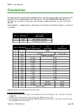
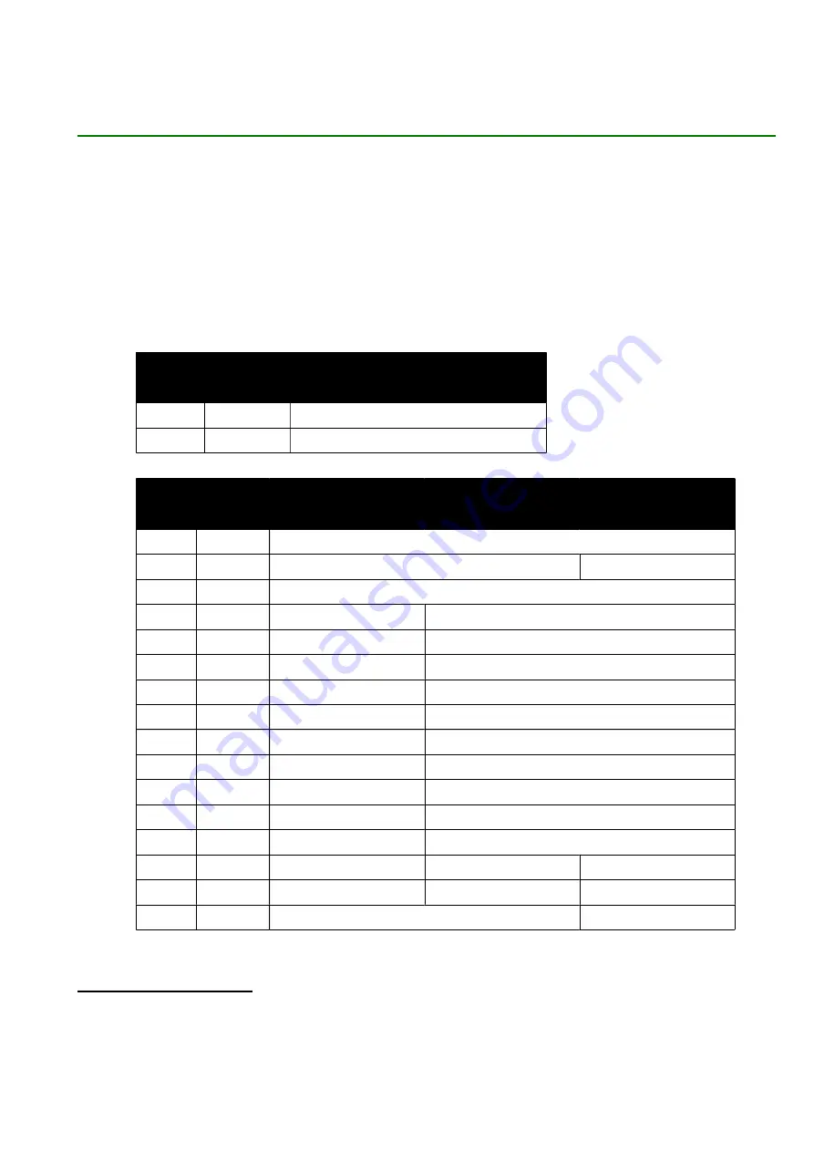
For each connector the pins are numbered from 1 up-to the total number of pins present. All
connectors have a
square pad
on the PCB layout. That pad
identifies the first pin (nr. 1)
.
The dual row connector J5 uses the normal header numbering scheme: an even row and an
odd row.
On the +, signal polarity is also shown on the bottom of the PCB by plus (+) and minus
(-) symbols.
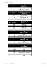
Pin nr
Direction
J2, J3, J4
PWM outputs
1
OUT
Load negative terminal
2
OUT
Load positive terminal
Pin nr Direction
J5
Pololu / 4-axis mode
J5
5-axis mode
J5
PEPPER board
1
-
GND
2
IN
#DISABLE
+5 Volt supply
3
OUT
#STEPPER_IO_SELECT
4
OUT
#Z_ENA
B_DIR
5
OUT
#Y_ENA
B_STP
6
OUT
E_DIR
A_DIR
7
OUT
E_STP
A_STP
8
OUT
Z_DIR
Z_DIR
9
OUT
Z_STP
Z_STP
10
OUT
Y_DIR
Y_DIR
11
OUT
Y_STP
Y_STP
12
OUT
X_DIR
X_DIR
13
OUT
X_STP
X_STP
14
OUT
#E_ENA
SPINDLE
#ENA2
15
OUT
#X_ENA
AXES_ENA
#ENA1
16
IN
Do not connect
SPI_IN
Signals preceded by a hash-sign (#) are active low.
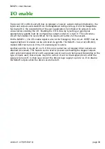
† If JP4 is open, this pin acts as (active low) disable input with on-board pull-up. See “I/O enable” description
on page 30.
‡ If JP4 is closed, this pin is the +5 Volt supply for the PEPPER add-on module.
†† JP3 should only be closed when attaching a PEPPER stepper driver board to J5. This signal connects directly
to the BeagleBone (3.3 Volt levels)!.
version 1.4.9 (09/04/14)
page 38


