Electrical Specifications and Installation
AMG-LP Hardware Manual
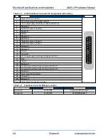
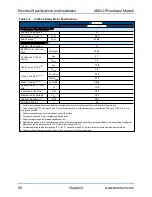
Table 3-3:
25-Pin Feedback Connector Pin Assignments [AZ and EL]
Pin
Description
Connector
1
Signal shield connection
2
Over-Temperature Thermistor sensor
3
+5 V power supply (internally connected to Pin 16)
4
Reserved
5
Hall Effect sensor, phase B
6
Marker-N
7
Marker
8
Reserved
9
Reserved
10
Hall Effect sensor, phase A
11
Hall Effect sensor, phase C
12
Reserved
13
Reserved
14
Cosine
15
Cosine-N
16
+5 V power supply (internally connected to Pin 3)
17
Sine
18
Sine-N
19
Reserved
20
Common ground (internally connected to Pin 21)
21
Common ground (internally connected to Pin 20)
22
Reserved
23
Fault output from encoder
24
Reserved
25
Reserved
Case
Signal shield connection (to case)
Table 3-4:
Feedback Connector Mating Connector
Mating Connector
Aerotech P/N
Third Party P/N
Backshell
ECK00656
Amphenol #17E-1726-2
Connector
ECK00300
FCI DB25S064TLF
24
Chapter 3
www.aerotech.com


